1/3/2022 – 1/16/2022
Summary: Spent the last 2 weeks disassembling and reassembling virtually every part of my 3D printer except for the frame and the motors themselves. Learned the JGAurora Magic is a seriously flawed printer that they themselves barely support. Lots of components are slightly modified, making the printer incompatible with most mods. I didn’t know much of anything about 3D Printing, and now I could probably build one myself from scratch. Mine still doesn’t work though. Currently held up on some firmware issues, along with compatibility issues with the LCD the Magic came with. Trying to put together something that can actually print with ~1mm precision, with enough quality that I could hand out the prints to people as gifts and they wouldn’t look at it like it’s some hot garbage I just gave them. I also started learning FreeCAD and 3D Modeling is starting to click and make sense for me as well. Hoping to have the Printer stuff configured and ready to just, print and go by the end of B.
Notes Textdump
Lab
Sprints
Anomalocaris
Resources List
Monty Choy Hardware Interview Questions
1
Digital Design HQ Discord #Resource Dump
2
EEVBlog Power Supply Design Series
3
Intel FPGA Technical Trainings
3
Digikey intro to KiCad
4
FesZ intro to LTSpice
4
Art of Electronics
5
Bitsolver
5
Nandgame
5
3D Printing Dive
Ultimate Calibration Guide
https://teachingtechyt.github.io/calibration.html#intro
Things
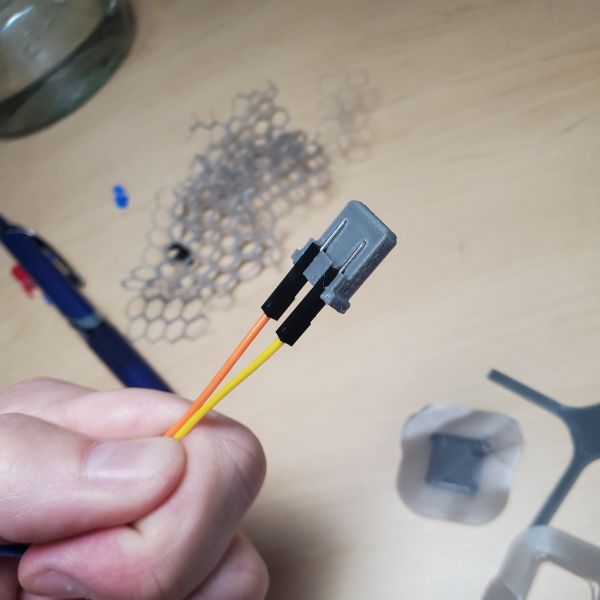
Dupont Adapter 2 Pin
https://www.thingiverse.com/thing:5167475/files
Youtube Videos
First 24 Upgrades & Mods for my Ender 3 Pro – Part 1
https://youtu.be/kG_YKeJDaX8
The Ultimate Guide to Perfect 3D Prints
https://youtu.be/YPAXeBuq9qU
Revised: 3D Printing – 13 Things I Wish I Knew When I Got Started
https://youtu.be/LvGKfevdf_Q
Watched a bunch of videos on 3D Printing and 3D modeling, 3D printer mods and calibration.
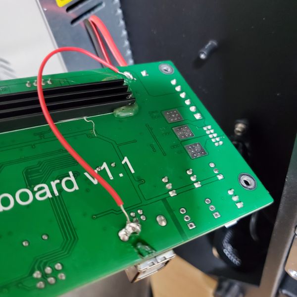
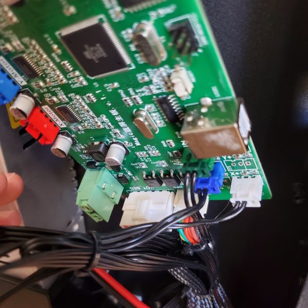
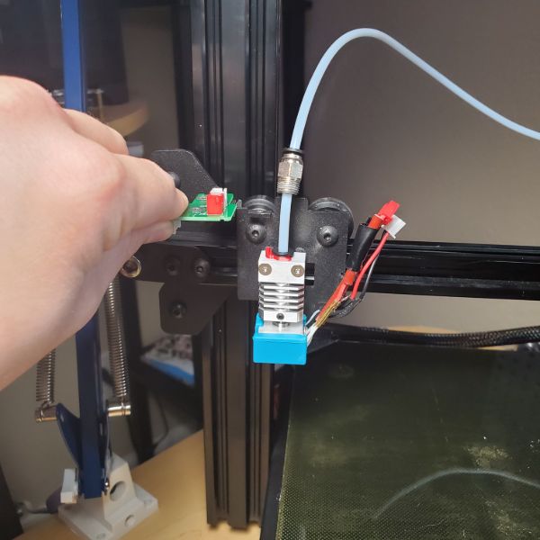
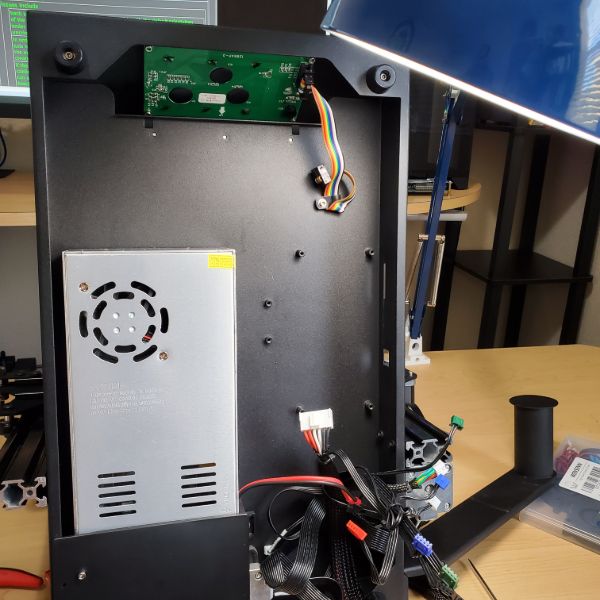
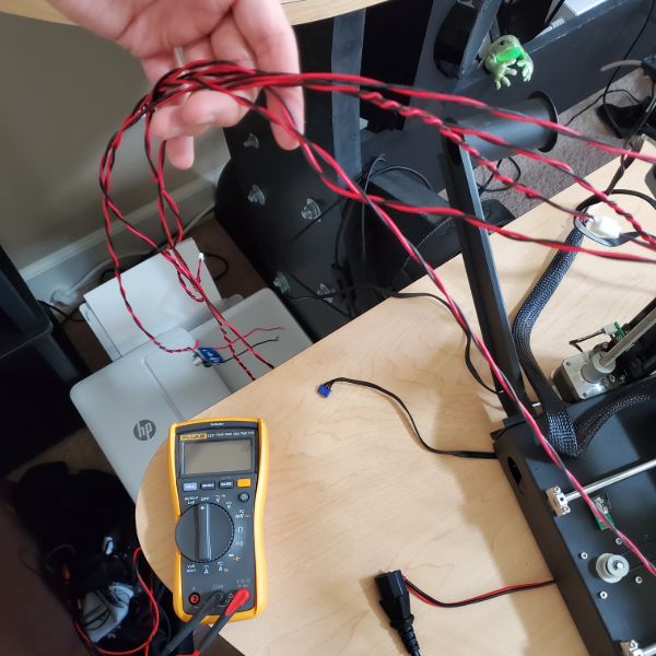
A review of my JGAurora Magic printer indicated there are numerous manufacturing defects throughout the design of the printer. The most significant one I wanted to address was the fact that the ground pin of the USB port for computer connected was simply not connected to anything. I jumped it to the housing of the USB, and then again to the ground of the power supply.
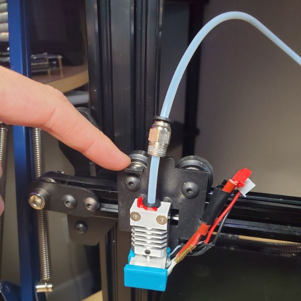
I also tighted the belt, the previous belt tension was held by two zip ties. Now the two ends of the belt are met with meshed teeth behind the extruder and I used a wire terminal crimp piece to crimp the rubber belt togeter, and then adjusted the tension manually.
Finally I manually leveled the bed until the print quality was good again.
I have two upgrades in mind. The first and more important one is to get some quieter fans for the extruder head. I hate how loud this thing is enough to not want to use it.
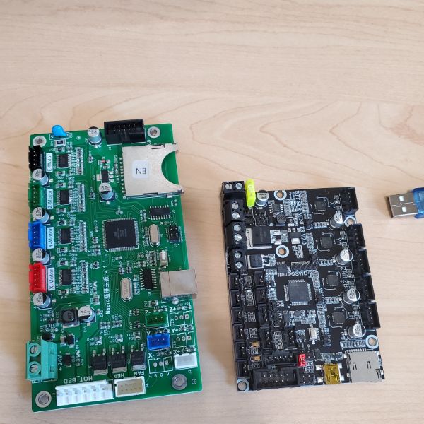
Second, I plan on getting a new motherboard for the printer along with the touch leveler. This will result in quieter stepper motors and a soft-leveled bed, further increasing print quality and decreasing noise level
After that, I’ll consider setting up octoprint, and maybe printing other mods for the printer, or getting a new print bed. Octoprint seems like it’ll be prohibitive since RPis are out of stock and very expensive right now.
I updated the firmware now that the USB is safe to use, and started using Cura’s Print to USB option so I can fiddle with the speed and temperature settings. This required re-leveling because the GCode is different from whatever my SD card designs from last year had. I also increased temperature, changed layer size, print speed, etc.
Since re-leveling is taking up a lot of my time, I think it’s worthwhile to get the leveling probe now, so I don’t end up spending too much time just fiddling the gears and reprinting to check
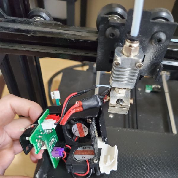
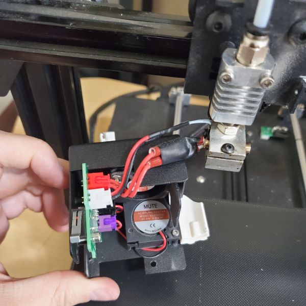
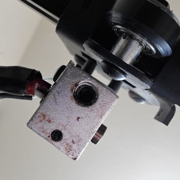
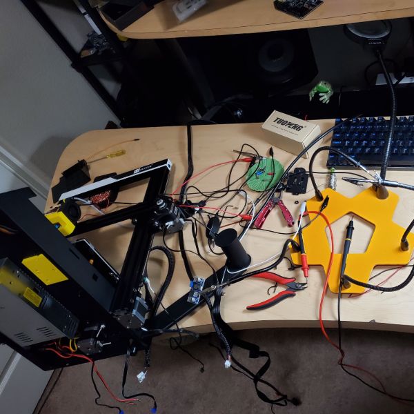
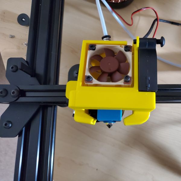
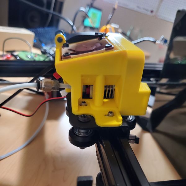
Extracted the fans from the extruder head. I also clipped off the burnt end of the feeder tube since it was darkened and clogged. Cleared out the extruder with a key and wiped it off with ipa and a qtip
the fans inside are 24VDC/0.2A and are both 30mm x 30mm x 10mm. 4.8W for something so small…
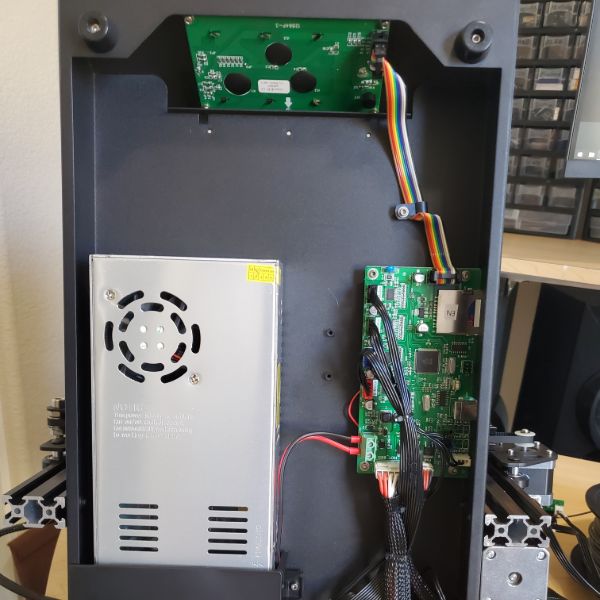
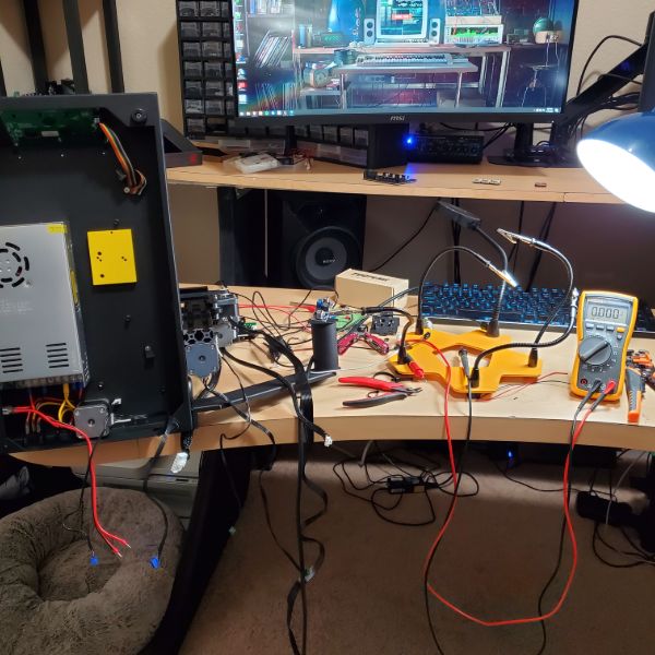
PSU is a pain to disassemble. The fan inside is 12V/0.20A @ 60mm x 60mm x 15mm. It’s not too loud, but I could replace it while I’m at it.
I need to check the PSU terminals for a 12V line so I don’t have to purchase a buck converter. Or, I can tap off of the 12V line that feeds the internal PSU fan, but my gut tells me that’s not a great idea/the best solution
While disassembling the underside PSU, I also realized I’ve been resting the printer on its back and thus on the lead screw, so now I need to take it out and roll it on a flat surface to check if it’s warped, and if it is, buy a new one… My tentative solution is to just rest the frame on a rectangle to create some space so the lead screw isn’t just taking it
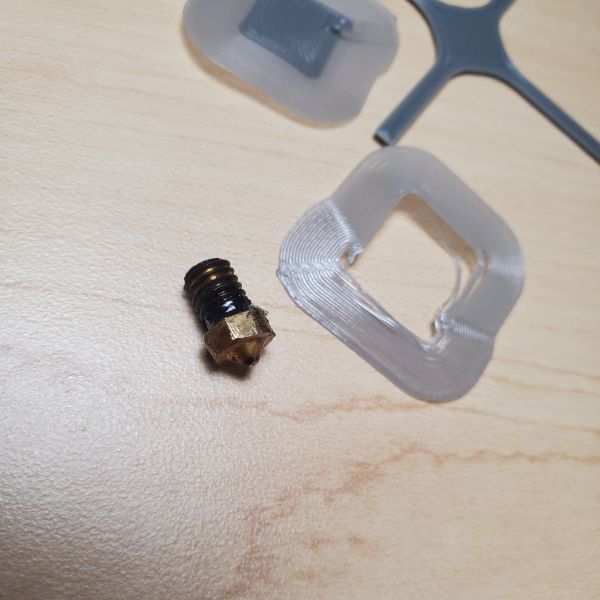
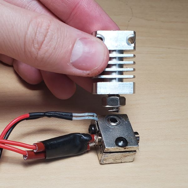
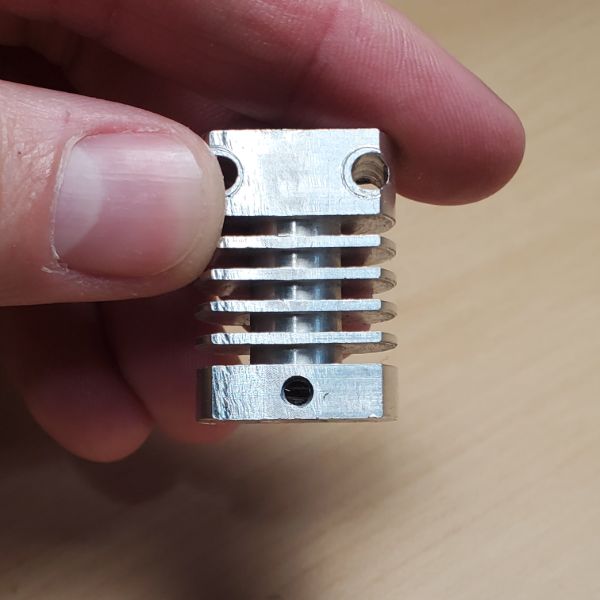
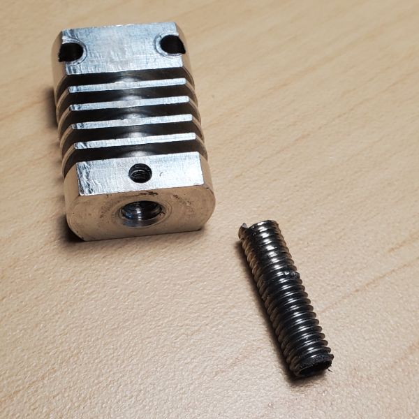
Snapped the heat brake trying to disassemble the hot end. There was a lot of goop and corrosion on it so I’m guessing it was a close cause to begin with. This means I need to buy a new hotend and spend roughly the cost of the printer on upgrades overall
Done for now
Purchase List – $250
Order
Difficulty
Mod
6
6
Buck Converters
7
6
Noctua Fan
Blower Fan
5
5
SKR Mini E3 Control Board with BL Touch
3
1
PEI Bed Sheet
1
4
Micro Swiss All Metal Hotend
2
2
Compression Springs
4
3
Aluminum Extruder Head
Mods Arrived, Time to Install Them
Springs have to come before bed
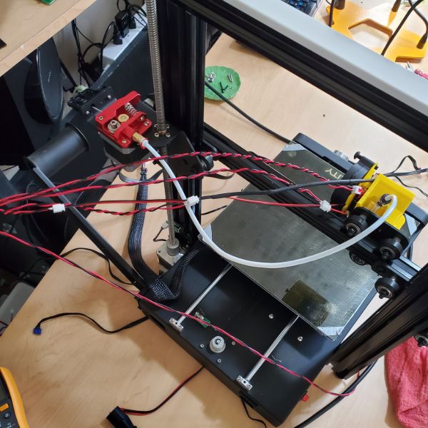
Springs were a pain, took out some stock washers so the new springs were more flush, had to tighten them down. Wondering if cables are on the same side or if I rotated the bed during this process
PEI bed sheet is interesting, I don’t think I got all the air bubbles down but the surface is definitely smooth and flat. It makes my glass bed look yellow/sepia colored. Duct tape on the corners still seems to work fine for fixing the bed in place. The new springs are much tighter
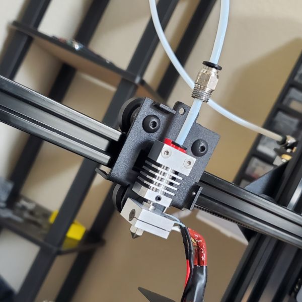
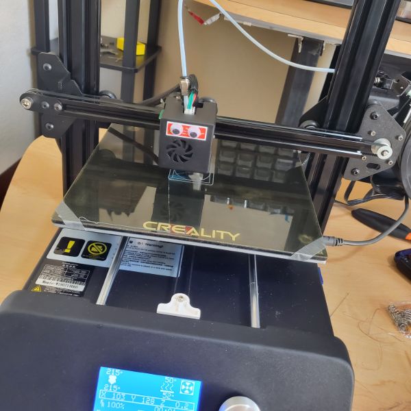
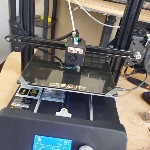
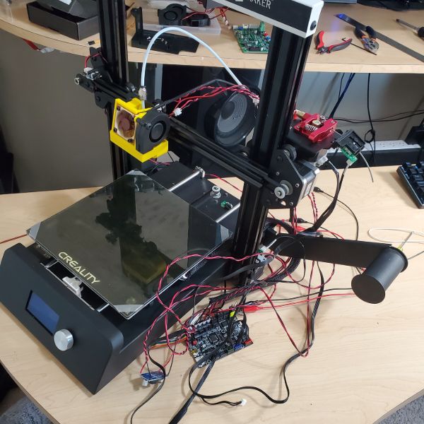
constructed all metal hotend, installed, leveled bed, and started test prints
even hastily calibrated, the prints are coming out better than the best i could do with the previous setup
For the all metal hotend, I set Retraction from 6mm down to 1mm
Bed Leveling feels strange, the back right spring adjuster head seems ready to fall off at a point where none of the other ones are. Maybe I needed to screw the bolt in a little more?
I also had to adjust the Z-axis stopper height to the new bed/nozzle
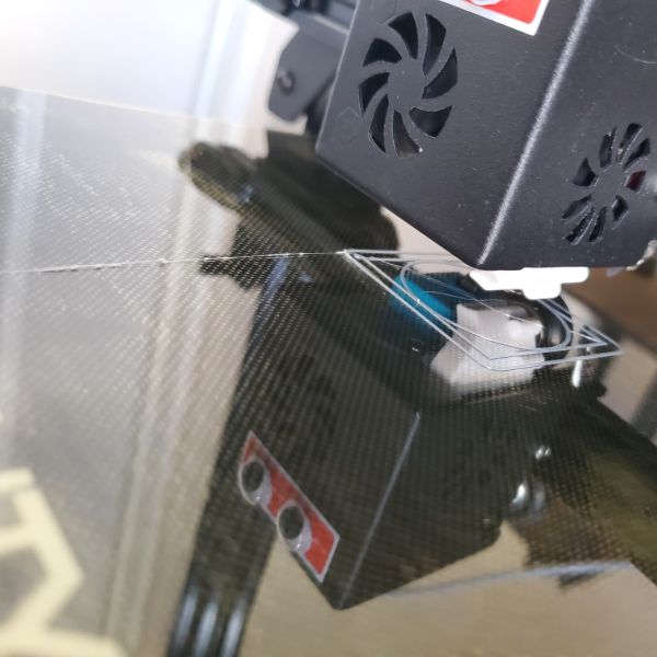
There was an issue with the printer printing about 10mm too high above the bed when printing from usb. After I printed an old file on the SD card, it started working again
I figured out that if you home the printer on the printer, and then send the print from usb command, it seems to work fine, but homing on Cura doesn’t seem to dissolve the extra height issue. It also prints from SD card fine
for the aluminum extruder, it installed just fine. It’s worth noting that the edge of the spring can get caught on the downhill slope/depression in the lever arm and cause the spring to “click” when the arm is squeezed. I fixed this issue by reinstalling the spring flipped around
I think I may have fully flipped the bed and caused the cables feeding the hot plate to twist. I can fix this by unplugging it from the motherboard side, since the cables are soldered directly to the bed.
No clogging on the hotend so far, it just. works. It’s the only piece I haven’t had any explicit trouble with so far
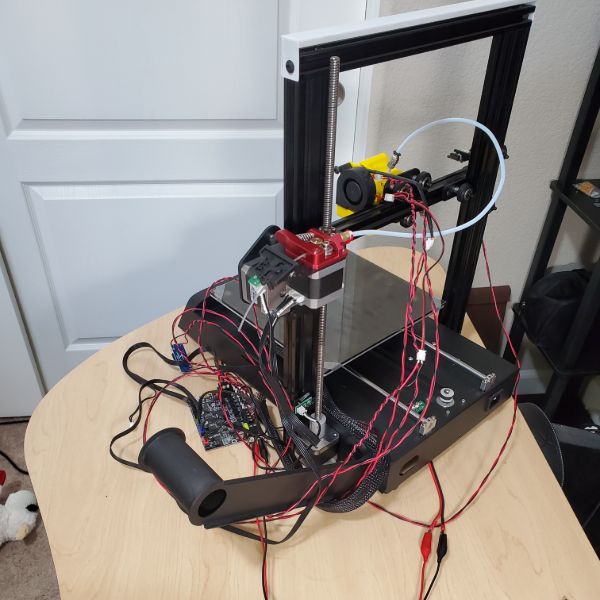
What remains to install, is the new motherboard, the BL Touch sensor, the creation and installation of a new fan shroud, and then the installation of the buck converters and the noctua fan, which will also require custom wiring.
Unfortunately, the noctua fan is the main thing that will quiet down the printer’s ambient noise, but it’s going to be the last thing I install.
Installing the new motherboard WILL reduce the stepper noise though, and that should help. Either way, I’m pretty sure I’m only barely halfway done, time/effort wise
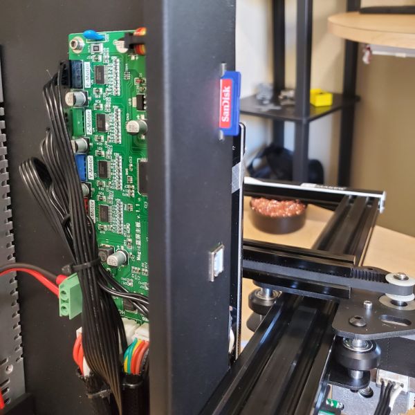
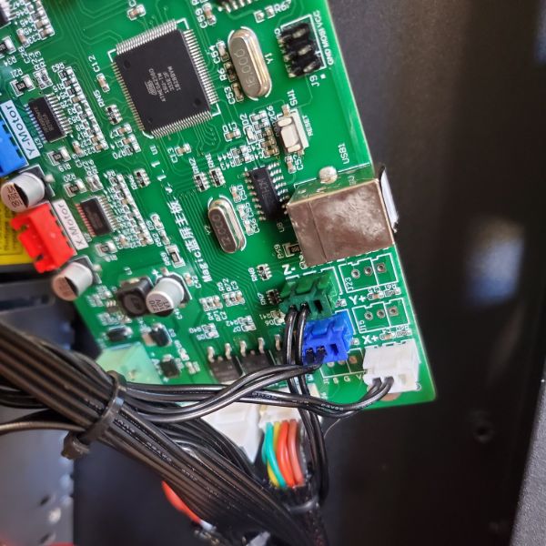
The new motherboard uses a different USB and has a microSD instead of a full SD. Which means I’m probably going to have to fashion my own holes in the hull of the printer, and then print an enclosure to hide the shame.
Along with that, I’m sure I’ll have to do a lot of soft calibration as well, maybe even PID tuning for the new motherboard. I imagine that process will take the most time and careful attention
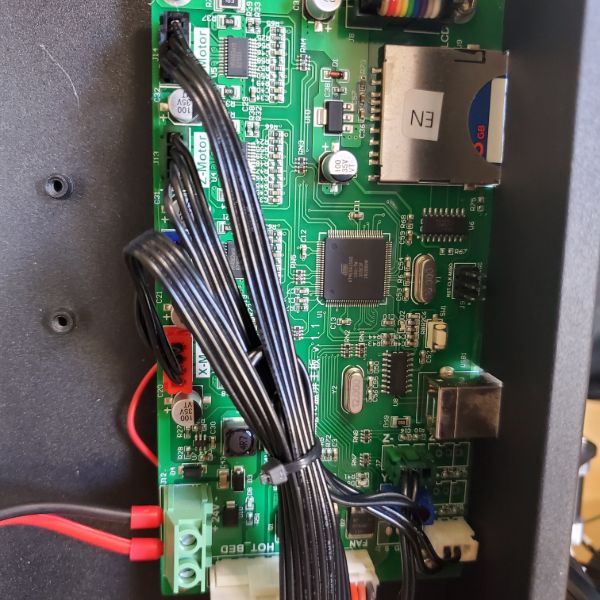
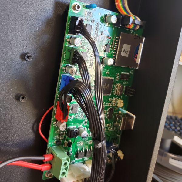
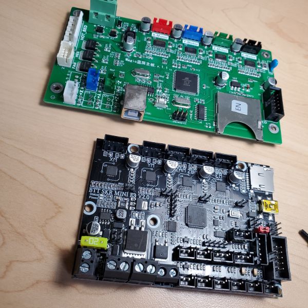
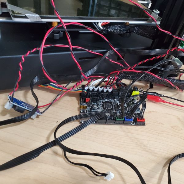
After investigating the new motherboard, I’ve realized a few things
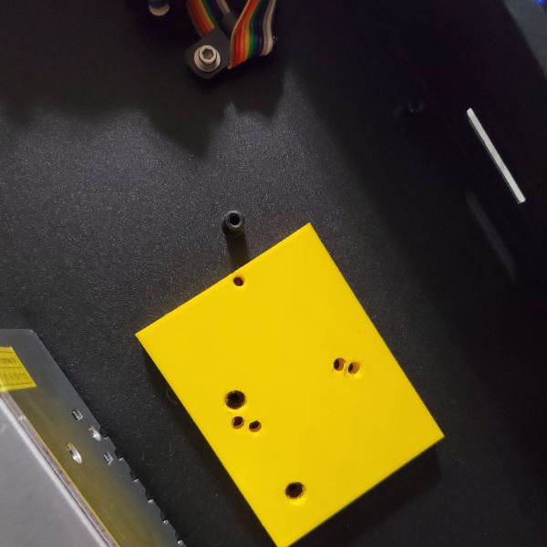
First, the new motherboard is designed for the ender 3 and so the dimensions and ports are completely different. I found that the microSD and the different USB port both fit in the hull hole sized for the full size USB, which is good. But there is literally no way to mount the new board using the existing mounting screw holes. No combination or angle makes it possible, and so that problem is going to remain unsolved for some time
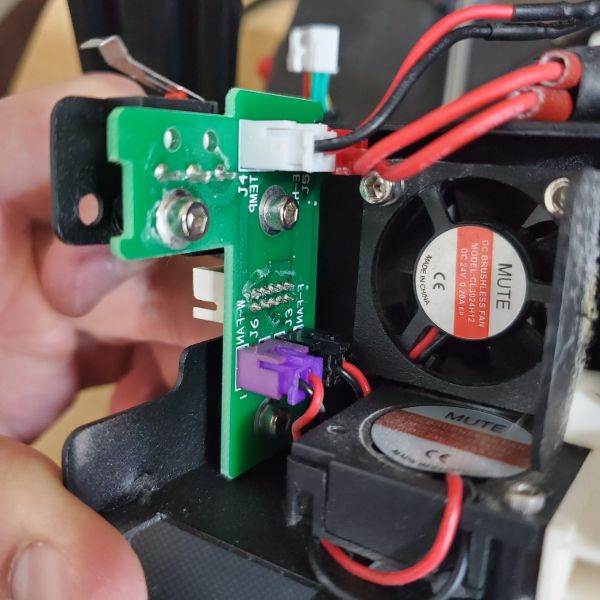
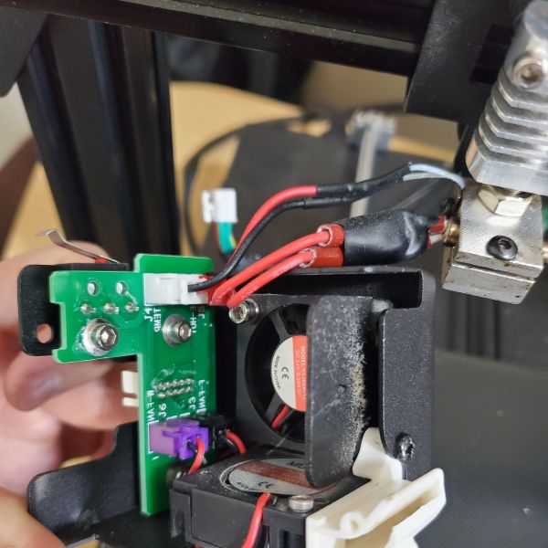
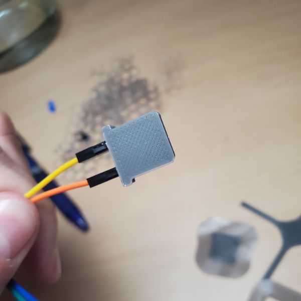
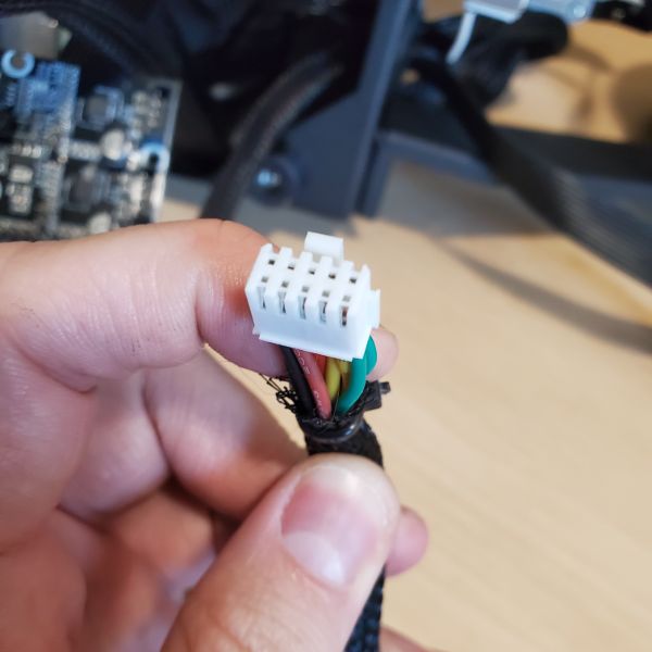
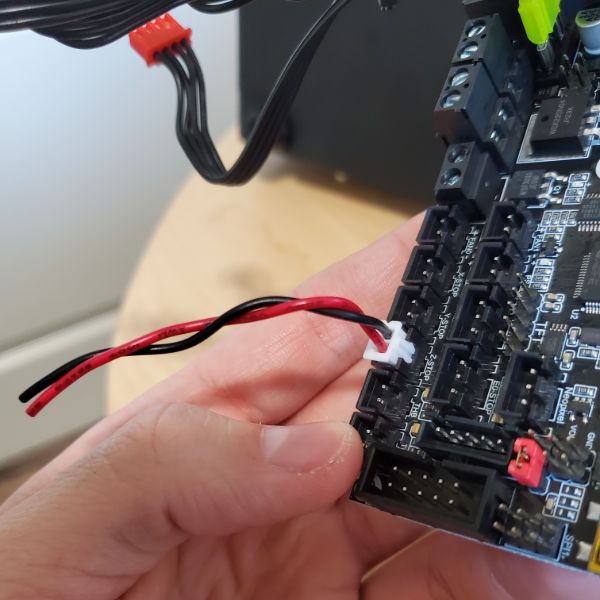
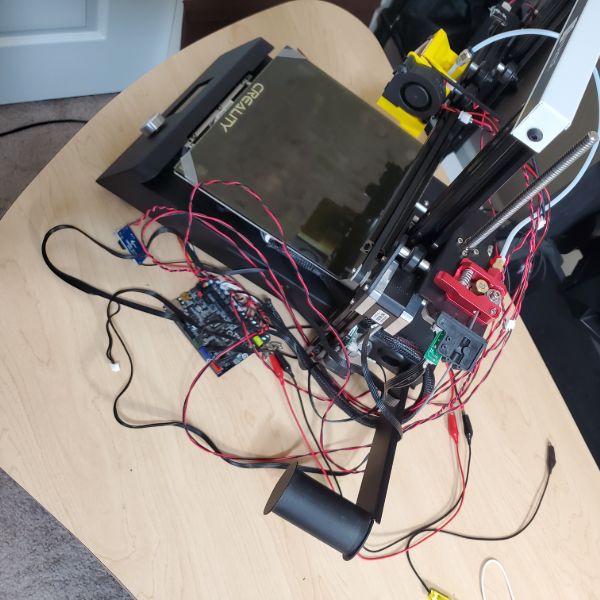
Besides that, the connector configuration is completely different as well. The hotend on the JG Magic has a 12 pin connector that addresses the thermistor, the x axis stop, the heater, the extruder fan, and the part cooling fan. In order to connect this printer’s equipment to the new board, I’m going to have to chop the 12 pin on the mobo side and manually crimp on new connectors for each pair of 2 wires.
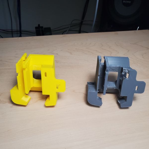
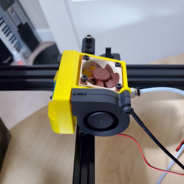
In addition to that, I’m probably going to have to remix a fan shroud as well, as the stock fans are 30mm but the smallest noctua fan is 40mm, and I’ll need to come up with a fan shroud compatible with the PCB handling everything on the hotend.
After I rewire everything, and find a way to rigidly mount the mobo, I can start thinking about installing the BL Touch and the Noctua Fan with the buck converters, but that time is not now unfortunately.
I think that the printer should be able to fulfill most of what I need out of it in its current condition, even if it is annoying and loud as fuck.
I should be able to address the fan shroud issue first, and install the noctua fan before I dig into the bottom and do all the rewiring. If I can manage that much over the next few days, then i can get rid of the biggest noise element. After that, it’s just the new mobo’s quieter stepper drivers, and if I’m really going for gold, I can find a way to replace the PSU fan as well. Maybe with another 40mm noctua or one of the spare 4x blower fans that will be arriving on Friday
Installation tutorial for new mobo – SKR Mini E3 V2.0
https://youtu.be/mtCz_-2zvZo
Satsana Fan Shroud
issues include
back support plate on the JG Magic isn’t compatible with the default orientation of the fan shroud. A potential solution to this would be to simply purchase the ender 3’s back support plate and install it on that. That would require uncrimping, recrimping the belt, and retensioning it.
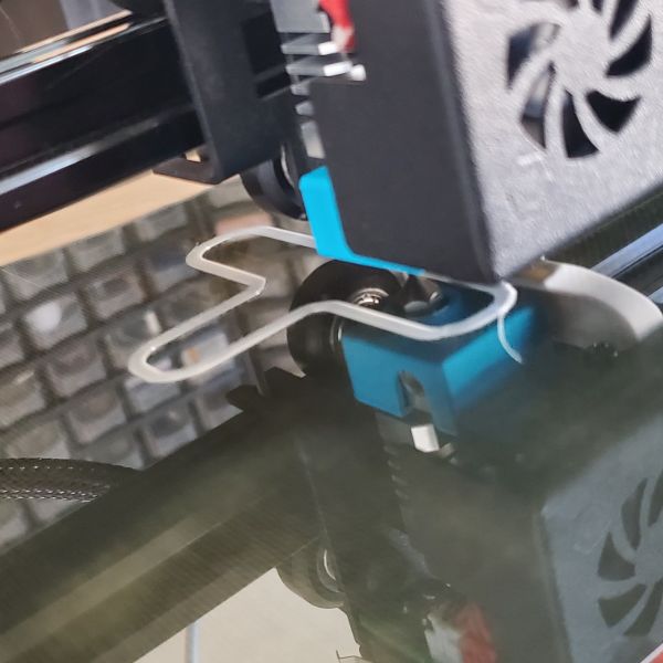
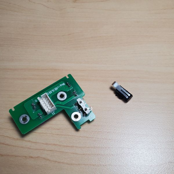
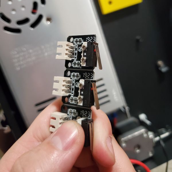
In order to install the satsana fan shroud, I will also have to remound the x-axis switch and move it from being attached to the hotend itself and mount it to the metal bar it collides with. This will also require a new board and some creative wiring as well.
If the X-Axis stop switch is removed from the system, all that remains is the cabling for the hotend, thermistor, part fan, and hotend fan. All four of these can easily be routed up along the cabling duct, or bundled just above along the bowden tube. This will require me to manually crimp and wire new 2 pin connectors that will be compatible with the new motherboard
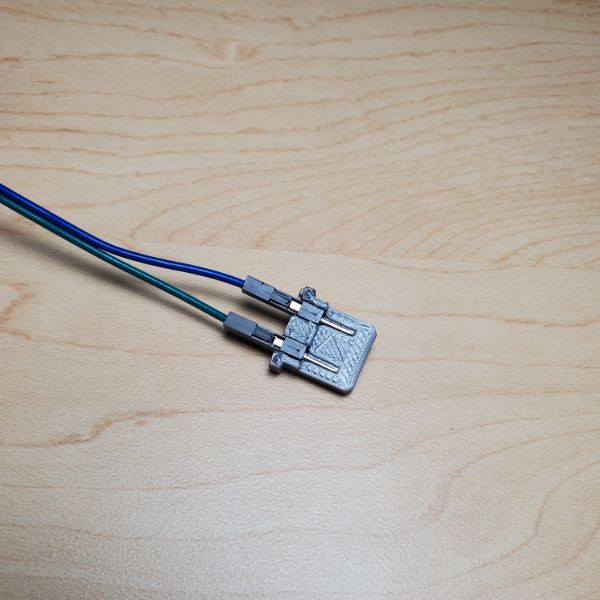
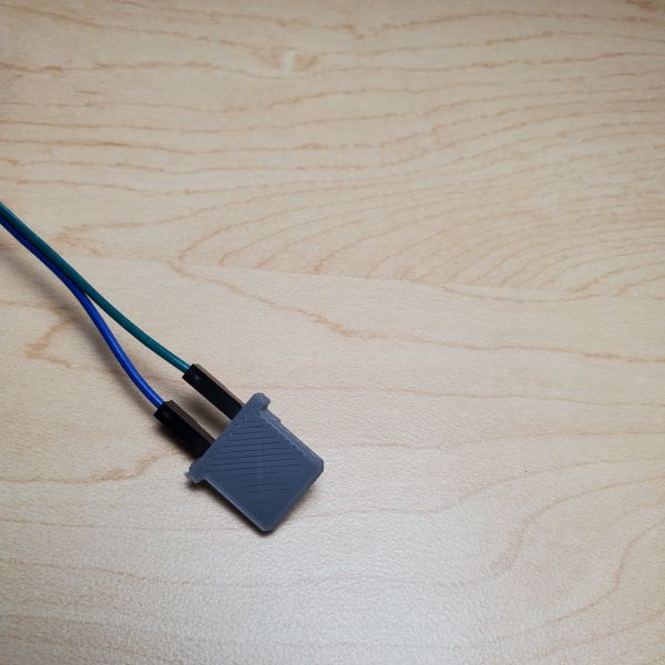
Solution, buy a new backplate and some mesh cable sleeving. Extract the X-Axis stopper switch and mount onto a protoboard, and then mount that board onto the metal bar. Wire it down to the new motherboard. Tentatively use the new motherboard un mounted and outside the hull of the printer. Crimp extension connectors from the hotend down the motherboard, print a new satsana fan shroud on jake’s printer so there’s less stringing. install everything at once (cringe)
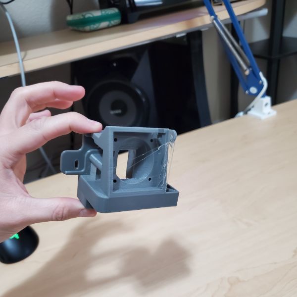
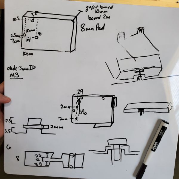
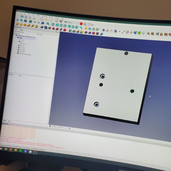
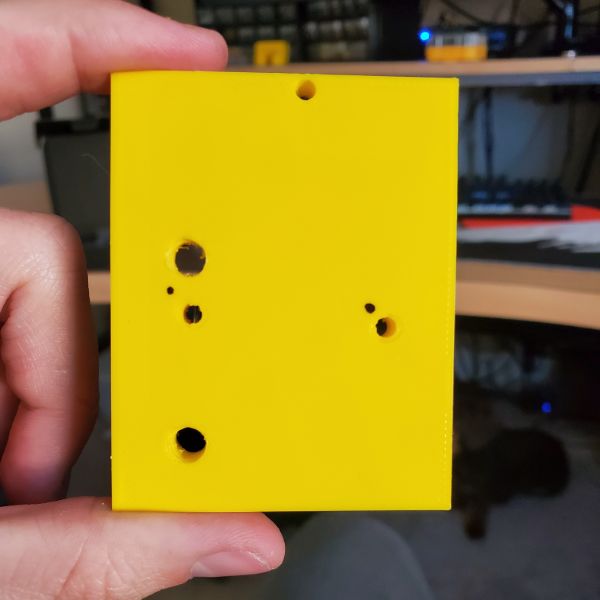
Motherboard adapter
Since the motherboard simply doesn’t align with any of the mounting holes the printer has, I decided that it would probably be easiest to just design a spacer/adapter that has screw holes to mount the 3D printed piece to the printer, and then has additional holes to mount the motherboard to the piece.
6
FreeCAD Tutorials
FreeCAD 0.19 – Basic Course – Part 1 – Your start with FreeCAD (EN)
https://youtu.be/u8otDF_C_fw
Tutorial
Workbench Selector
The Part Design Workbench is standard for designing 3D geometry/parts
Tutorial Recommended going into preferences and enabling Automatically Check/Refine model after boolean operation under Edit>Preferences>Part Design>General
Shape View>Maximum Angular Deflection to 6deg
Toolbars ARE rearrangeable
Rediscover Toolbars using View>Toolbars
Everything in the 3D view can be toggled visible or invisible
Select a part, and then press Spacebar to toggle invisible
Mouse over the 3D View control setting to see how to navigate
Views, and a button if you lose your piece
You can move, and close Combo View. Reopen using View>Panels
Select an element of the model, and under the Tasks tab of the Combo View, you’ll be presented options for modifying that element. For example, creating a Chamfer.
Grey elements in the Model Tab are invisible
Feature Editing Methodology – Only the most recent edit is displayed. You can go back through timestamps of the model’s forming by making previous steps visible. For the most recent step, view the bottom step
Some basic elements will be based on Sketches. Some extended features will be 3D Geomtry tool actions
If you go to an element’s geometry by double-clicking, it will open the Sketcher Workbench
File>New – Then Save Document
Always double check that you’re in the part design environment/workbench
After Creating and Saving/Naming a new file, create a new body element
You can also use the Combo View>Tasks>Create Body. Same thing
When you start with a basic shape, it’s called a “Part Design Primitive”
After selecting a primitive, the first thing FreeCAD needs is an anchor point. “Attachment” calls for it to be anchored to either another part or to an axis or plane
After that, you can define the usual geometric parameters. These primitive parameters can be edited later
This is what is meant by “Parametric CAD System”
The other option that doesn’t involve using a 3D Primitive is to start with a sketch
You still have to pick the base plane/attachment/anchor plane
Be careful with toolbars that don’t show themselves entirely
Circle tool makes a circle
Constrain circle defines a parameter/dimension of that circle within the sketch
Adding lines via the line tool that are just a radius of a pre-existing circle means FreeCAD will automatically place a constraint on them. This means that if you change the radius of the circle, the additional radius lines you added will automatically adjust to the new parametrically defined radius
The Sketch becomes overdefined if there’s more than one closed geometric shape, so you can use the Trim command to cut out unnecessary lines
Once you’re satisfied with the shape and can confirm it is fully constrained, the sketch is complete and can be closed
From there, select the sketch and use a 3D manipulation tool to expand the sketch into 3D space (parametrically)
FreeCAD 0.19 – Basic Course – Part 2 – Sketcher Introduction (EN)
https://youtu.be/-9KATZg1PqM
Tutorial
Sketching is the most important skill for creating professional 3D designs
The Sketcher Toolbar consists of tools for
Creating Sketch Elements
Dimensioning
Creating Constraints
The Sketch Combo View>Task Menu contains
Solver
Controls
Constraints
Pay attention to if the sketch is under-constrained, and how many DOF it has. For example, if I place the circle on the origin, it only has 1 DOF because it’s anchored to the plane. If not, it has 3.
The 3 DOF are X position, Y position, and Diameter
If placed on the origin, obviously it is locked to a specific X,Y and can only adjust its diameter
After creating constraints for the diameter and the X position of the circle (referenced to the origin point), the only DOF remaining is the Y position
Once the sketch is fully constrained, it will change color, from white to green, or whatever the settings indicate. This signals the sketch is fully constrained and ready for 3D work.
The principles are the same every time. Create a sketch element, and then provide dimensional constraints to that element until it is fully defined.
A single line has 4 DOF. X,Y for first point of line, X,Y for second point
After anchoring a point, solving 2 DOF, you can also solve the another by defining an angle between the line and an axis. HOWEVER, the length of the line will represent one more DOF
However, a fully defined line a shape does not make. A freefloating triangle can be made but the floating point will still need constraints in order to form a valid shape. Start thinking in terms of DOF
The symmetric tool is powerful. Select two points, and then a third to be the hinge around which the first two are symmetrical. It produced fun effects
Constrain first, Dimension Later
The PolyLine tool is even more powerful. Press M while placing a segment to set it to move perpendicular, or circular to the previous point
FreeCAD Lesson 01 – Turners Cube
https://youtu.be/_HEvhclR4-o?list=PL6fZ68Cq3L8k0JhxnIVjZQN26cn9idJrj
Tutorial
Select a face of a 3D Object, and then click the create sketch button to start drafting a sketch that will appear on that 3D face
Change the view of the 3D object
6
Automate Boring Stuff with Python
7
C++ for Embedded Systems
7
12 Sprints until 6 month mark
AB CD EF GH IJ KL – be there by M
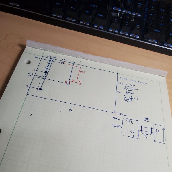
Protoboard Electrical Box v1
Using an old 1s relay timer from like 2 years ago
dimensions:
70mm x 30mm x 1.5mm
2mm diameter screw holes in each corner, 1mm in from each corner
expand 3mm on every side:
76mm x 36mm x 25mm INNER DIMENSIONS
3mm space below board for wires
2mm thickness walls
Outer Dimensions
80mm x 40mm x 27mm