
1/17/2022 – 1/30/2022
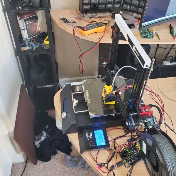
Summary: My goal was to have the printer calibrated, tuned, and ready to just print and go by the end of B, and I was able to get there with a few days to spare, which I’m happy about. Picking up where I left off on A, the wiring for the printer was all complete, so I moved on to cable management, buttoning the whole thing back up, and then moving on to calibration. While the wires were sprawled out everywhere, I tried to print the mount for the BL Touch probe, but one of the wires snagged on the frame and tore out the wire on the Thermistor, rendering the printer completely useless. After I got the new thermistors and installed, the printer worked again no problem (Which was something I was worried about). Cable management was pretty straightforward and went better than I expected. At this moment, I still haven’t reprinted the motherboard’s mounting plate, but it doesn’t seem to be complaining.
Once the printer was printing again, I found that the printer was misconfigured in the firmware after some changes I made: the prints were coming out mirrored along a horizontal axis. A tentative fix was to just mirror it in the slicer, but I eventually figured out that I needed to flip basically every config concerning the Y-axis range and endstop logic, and then it worked as expected. A second issue was that the Z-axis of the prints were coming out at exactly half size. In response to that I just doubled the Z-Steps. The prints started coming out better after that.
After an entire week’s worth of calibration and testing and repeating prints, below are the settings I eventually landed on.
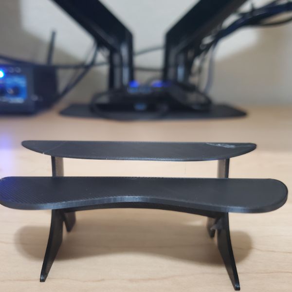
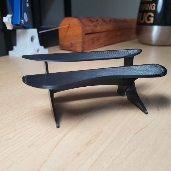
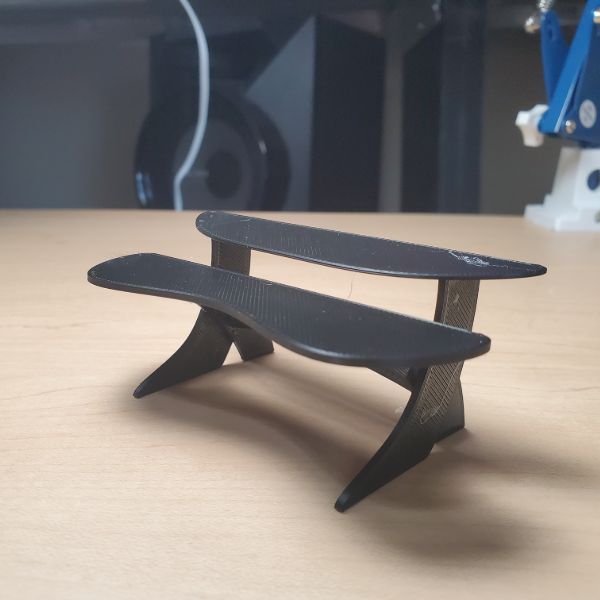
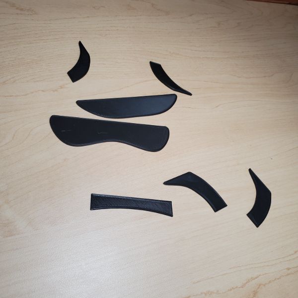
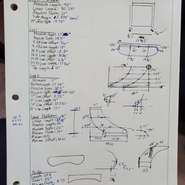
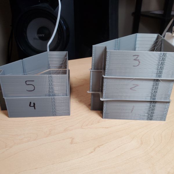
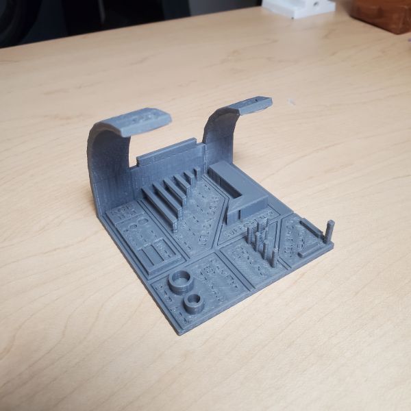
Once the printer was calibrated to my satisfaction, and after I had to buy some 0.01mm calipers to verify that satisfaction, I decided to break in the printer by creating a CAD model of the Megadesk. The desk was based on paper drawings with absolutely no measurements or numbers on them. Since I basically built the desk from single-copy stencils, there’s no digital copy of the design files. Now there is. The whole process went by much faster than I was expecting. Printing them out and assembling the mini megadesk was way more fun and easy than I was expecting. It was rewarding after putting so much time and money into the printer. The mini megadesk is inches to mm, so 1/25.4th size.
Layer height 0.2
Wall thickness 0.4
Print Temp 230/50
Flow 90%
Print speed 60mm/s
Retraction 3mm
Retraction speed 30mm/s
Prime speed 40 mm/s
Z Hop 0.4
Print Cooling 100%
Print Acceleration 1400
Junction Deviation 0.21
Linear Advance K=0.55
X range: 210mm
Y range: 230mm
Probe Offset
X: -43mm
Y: -10mm
Z: -1.70mm (many passes on this)
Notes:
B
3D Printing Dive
Objectives:
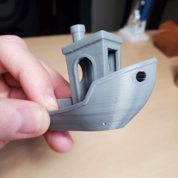
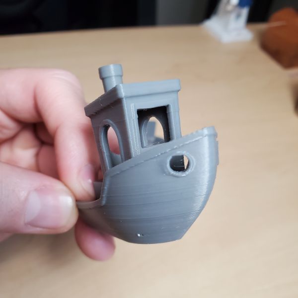
Optimize Calibration Cube
Pass Clearance Castle
Not paying $3 for an STL
Model Megadesk
Settings:
Layer height 0.2
Wall thickness 0.4
Print Temp 230/50
Flow 90%
Print speed 60mm/s
Retraction 3mm
Retraction speed 30mm/s
Prime speed 40 mm/s
Z Hop 0.4
Print Cooling 100%
Print Acceleration 1400
Junction Deviation 0.21
Linear Advance K=0.55
X range: 210mm
Y range: 230mm
Probe Offset
X: -43mm
Y: -10mm
Z: -1.70mm (many passes on this)
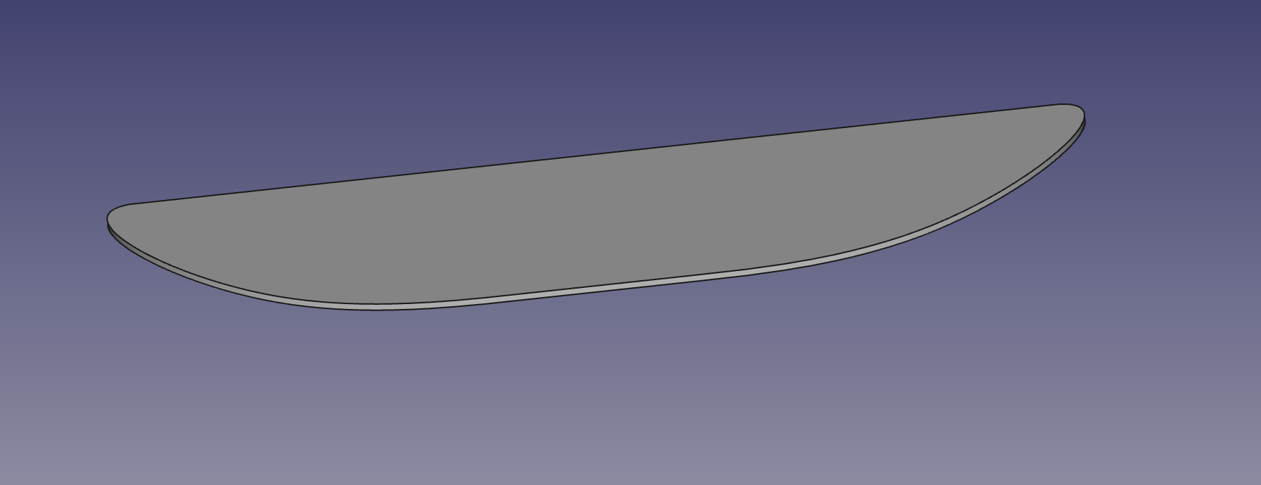
Megadesk Modeling
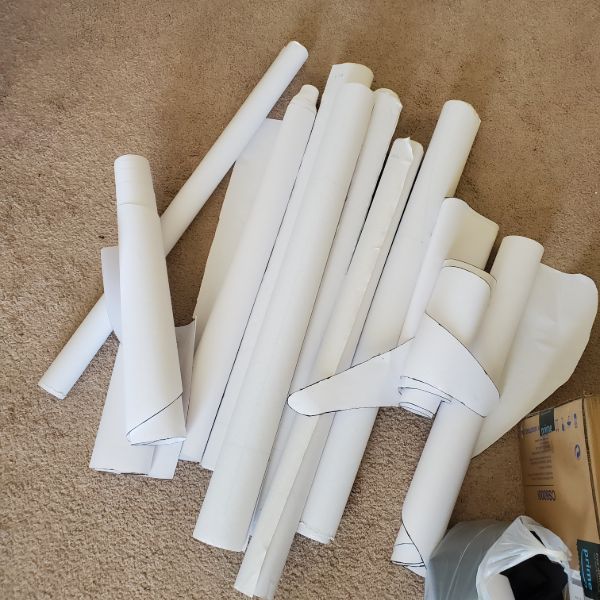
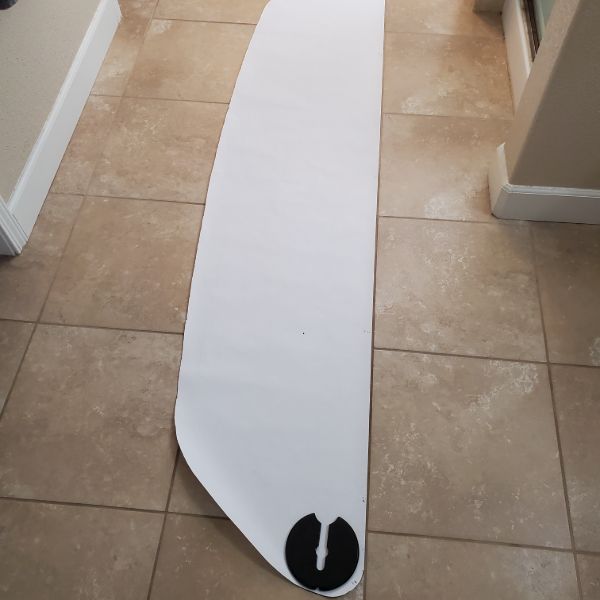
Modeling the upper desk piece went pretty well. I’m aligning the paper pieces that I used as Stencils in the original construction onto the floor tiles in my bathroom. After measuring the tiles and the grout between them, as well as the pieces themselves, I’m able to get good, accurate measurements on the dimensions of the piece.
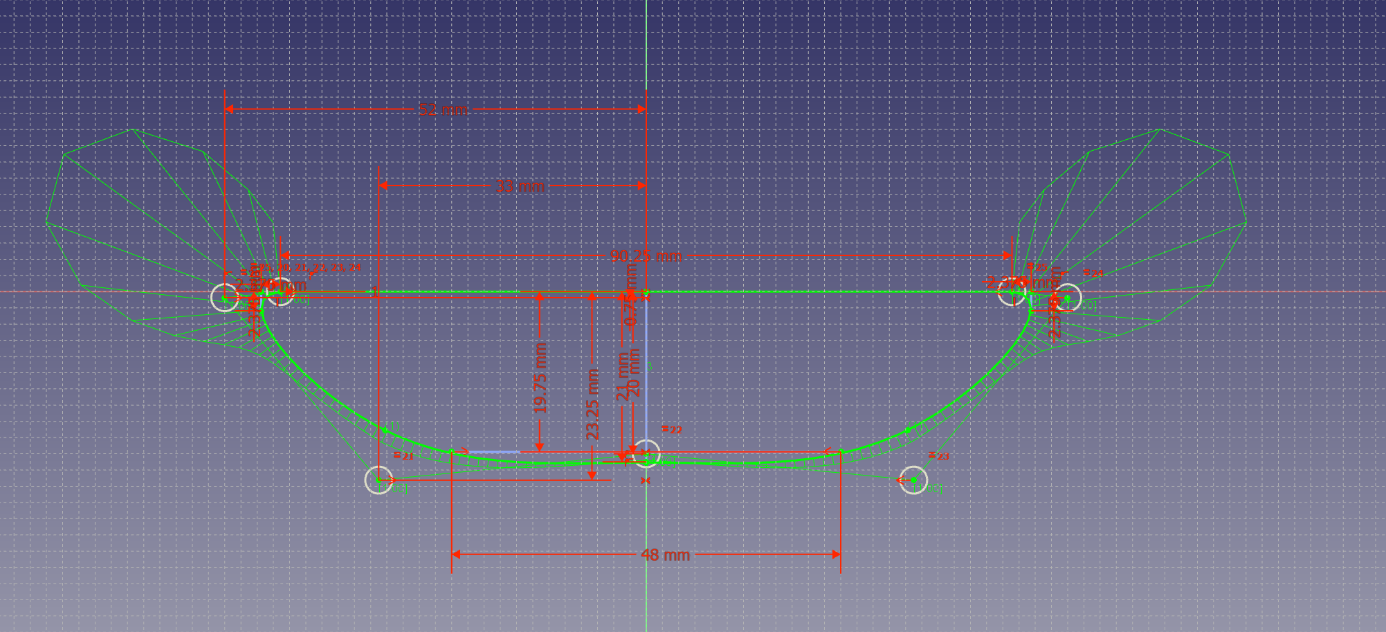
Since it’s curved, I have to use the curve tool in FreeCAD, which is actually pretty easy to use. I was able to figure it out, and the piece required about 5 points to guide the curve into place.
What I’m doing is measuring points along the curve, and figuring out exactly where they lie relative to the back/center of the piece. And then creating construction lines in FreeCAD that I can freehand wrap the curve onto. With a sufficiently large sample of points, this becomes a trivial process for modeling the curves of the desk accurately. It just requires careful measurement.
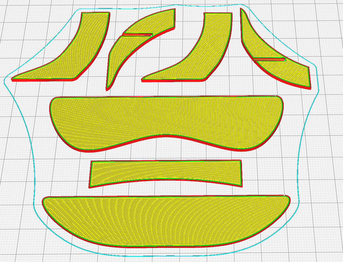
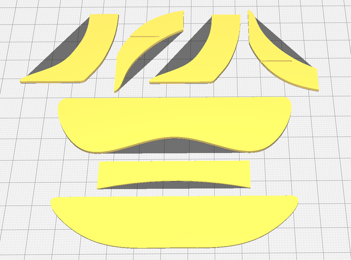
Went really well, was pretty easy to get measurements towards the end of the process
Measured each leg piece once, designed the cut for the bridge, and then mirrored the second instance to get it aligned properly
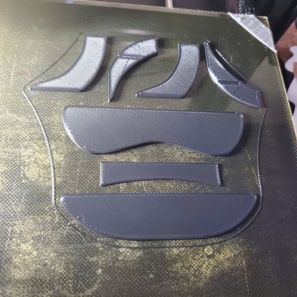
Printing now, takes about 1 hour, the whole thing is scaled inch to mm, so it’s 1/25.4 scale, which is just about perfect for a desk
Only took about 4 hours total to measure, sketch, model, and slice
This was WASY easier than I thought it was going to be
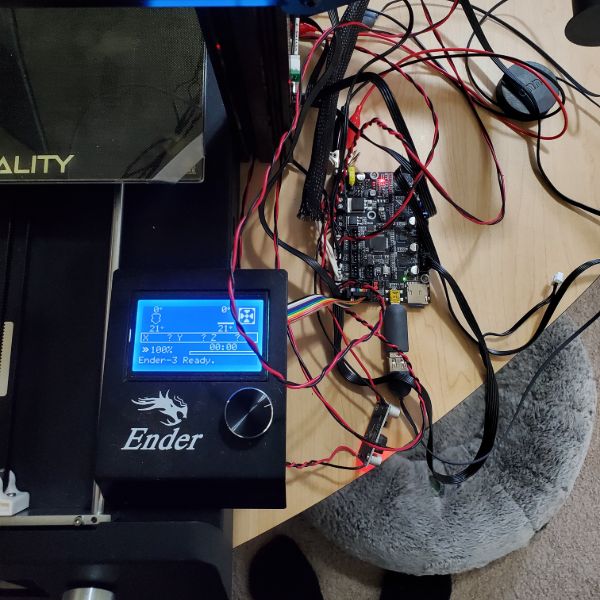
Flashing Firmware
Since the LCD the Magic came with isn’t compatible with most other boards due to its modified pinout, I’m going to borrow Jake’s LCD from his Ender 3 in order to debug firmware and make sure it’s working.
Otherwise, I have to buy my own for $30 blind, or keep trying to get Cura to detect a printer that I’m not even sure is flashed properly.
Found a good video that shows the process for editing and compiling the firmware too.
https://youtu.be/0tRXUBvcZ0o
I tried using the Arduino IDE to export the compilation as a binary file, but it still outputs a Hex file because I guess that’s what’s actually written
I also looked into tools like Hex 2 Bin, or even online web pages but something didn’t work when I used file upload for the .hex because it called invalid input. So I just dropped the issue.
Configuring Firmware
After I got the printer working and the motors responding, I couldn’t get it to auto-home.
After some basic troubleshooting with the endstop switches, I realized the printer thinks the switch functions are inverted. Meaning it thinks it’s already at the end stop. When I hold a dimension’s switch down and home that axis, it moves in the opposite direction.
Need to find the firmware setting for this so I don’t have to resolder 3 switches.
Changes:
Endstop Definition
// Specify here all the endstop connectors that are connected to any endstop or probe.
// Almost all printers will be using one per axis. Probes will use one or more of the
// extra connectors. Leave undefined any used for non-endstop and non-probe purposes.
#define USE_XMIN_PLUG
//#define USE_YMIN_PLUG
#define USE_ZMIN_PLUG
//#define USE_XMAX_PLUG
#define USE_YMAX_PLUG
//#define USE_ZMAX_PLUG
Endstop Logic
// Mechanical endstop with COM to ground and NC to Signal uses “false” here (most common setup).
#define X_MIN_ENDSTOP_INVERTING true // Set to true to invert the logic of the endstop.
#define Y_MIN_ENDSTOP_INVERTING false // Set to true to invert the logic of the endstop.
#define Z_MIN_ENDSTOP_INVERTING true // Set to true to invert the logic of the endstop.
#define X_MAX_ENDSTOP_INVERTING false // Set to true to invert the logic of the endstop.
#define Y_MAX_ENDSTOP_INVERTING true // Set to true to invert the logic of the endstop.
#define Z_MAX_ENDSTOP_INVERTING false // Set to true to invert the logic of the endstop.
Endstop Locations
// Direction of endstops when homing; 1=MAX, -1=MIN
// :[-1,1]
#define X_HOME_DIR -1
#define Y_HOME_DIR 1
#define Z_HOME_DIR -1
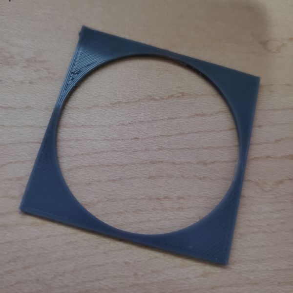
Adjusting Size for the new Fan Shroud
// The size of the printable area
#define X_BED_SIZE 220
#define Y_BED_SIZE 235
Manual Tuning & Calibration
Now that the firmware functions appropriately and can move the motors, manage heat, and push filament, I did some bed leveling
The Manual Probe function is difficult to work with and my duct tape gets in the way.
I’m going to have to re-level everything again once I put all the wires and boards back into the undercarriage. There’s also a rubber foot that’s just placed under the frame right now, which will probably shift everything by a bit
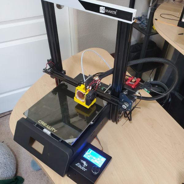
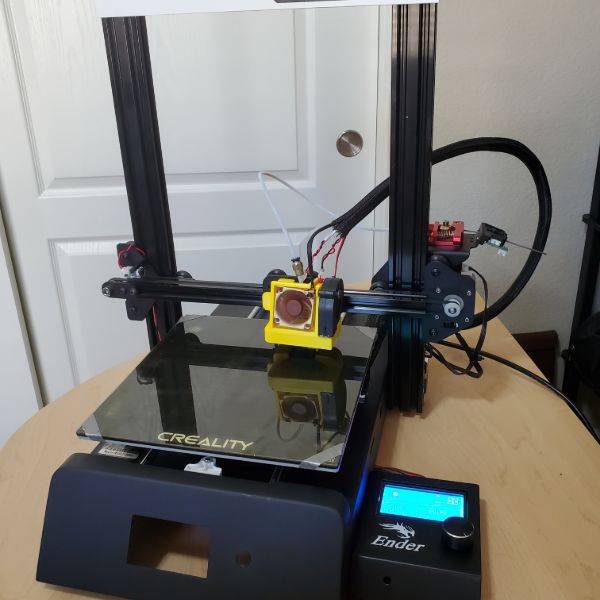
But after some fine knobbing and cleaning the bed, the printer is finally printing cleanly.
Next Steps
There’s an issue with the part cooling fan running at 100% all the time and it’s actually pretty noisy. I’m not sure how loud it’ll be in the closet, but I know I can set it to like 40% and forget about it.
Along with that, the part cooling fan isn’t flush against the air duct it’s supposed to be filling. I’m not sure if the right call is to seal it in with hot glue or to print something else, but for now it’s running inefficiently and loudly. This can be fixed. I can also just, turn it off, I guess.
On the bright side, apart from the part cooling fan, the printer is basically completely silent.
I don’t want to dedicate the Pi to doing OctoPrint for this, which means I’m going to just have to suck it up and move SD cards back and forth. This also means that I have to align the motherboard mount just right as well. Since the SD card slot won’t be accessible unless I buy an adapter, or do the mount just right, or I circumvent it and buy another Pi.
I also have to purchase a new LCD since the original one is incompatible. That will run me about 30 bucks and it might just be worthwhile to get the SD card adapter after all. It’s only $6 and will probably save me a lot of hassle.
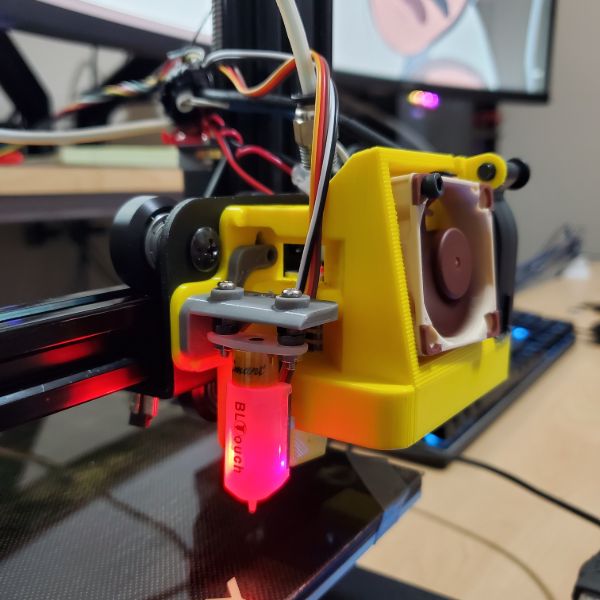
Along with all the wiring work that I’ve done so far, I also have the BL Touch sensor to install and calibrate as well. I’m not sure if it’ll be worthwhile to get the bed clips. I’ll have to reference the JG Magic review again
BL Touch will require an additional print, mounting to the backplate, and then editing the firmware, and then a new cable, and so I shouldn’t add the mesh sleeves until I’ve finished installing it.
Action
Connect via USB
Order new LCD and SD Extender
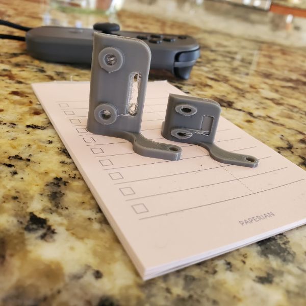
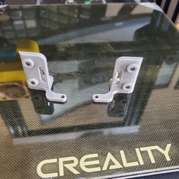
Print BL Touch Holder and Mount
Install BL Touch and run Cable
Edit Firmware to get BL Touch Working
Cursory Calibration of BL Touch Sensor
Print New Motherboard Mount Plate
Cable Management and Mesh Sleeving
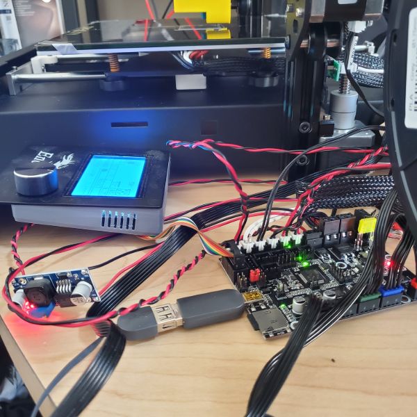
Mount Motherboard, New LCD Screen, and Buck Converter
Get it Pretty
Go Through fine Tuning/Calibration Guide until satisfied
Put it back in the closet
Thermistor Broke
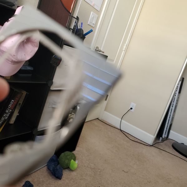
I went to print the mounting piece for the BL Touch so I could start finishing off the printer, and then everything went wrong.
One of the extruder head’s wires got snagged on the +X edge of the aluminum frame. When it tried to pull back, it couldn’t and the motor started grinding. When I came by to investigate, I tried to push it back before I saw the wire snag and thought the motor was locked. By the time I figured it out and released the cable, the thermistor had already broken one of its wires at the glass bead point, which as far as I can tell is impossible to resolder in a meaningful way.
This means I have to order a new thermistor, or more specifically a 5 pack of new thermistors, and the printer is completely disabled until Friday.
Order List
New Thermistors
Friday
New LCD Controller
Saturday
Micro SD to SD Extender
Monday
Review
Learn how to install BL Touch
Preliminary Cable Management
Review Calibration Guide
Explore Firmware more thoroughly
Continue FreeCAD drawings
Measure up LCDs
Look into quieter fans for PSU/Part Cooling
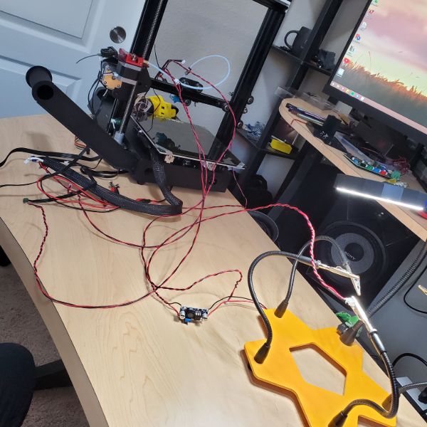
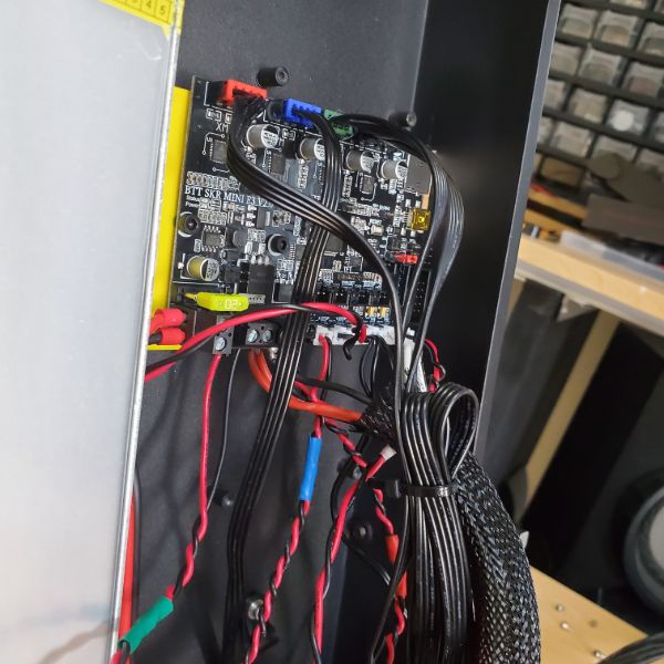
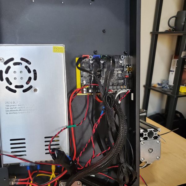
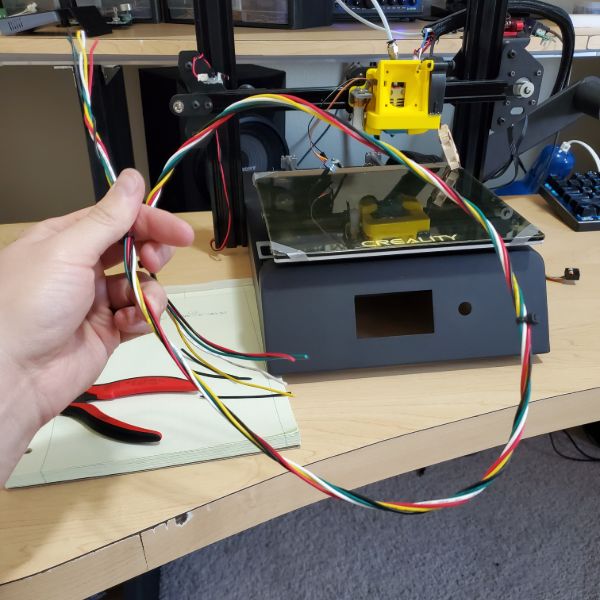
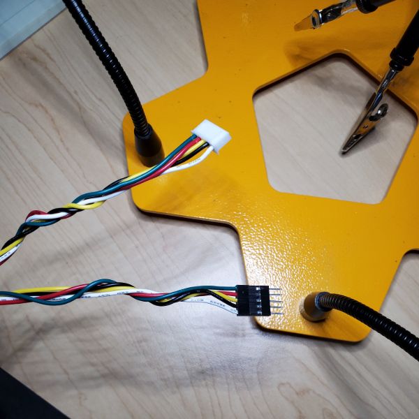
Cable Management
Starting off by hotglueing all the exposed wires/solder on the JST connectors I made.
Also wrapping colored electrical tape on both ends so they’re easier to keep track of
Print Head Color Code:
Heater
Red
Thermistor
White
Part Cooling
Blue
Extruder Cooling
Green
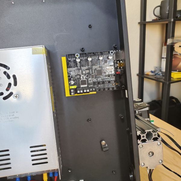
I managed to get the original mobo mounting plate to work by filling the drilled holes with hot glue and then forcing the bolts through them. It’s not the most stable solution, and there’s definitely some give, but the motherboard is fixed in place where it needs to be while I figure out how to organize the cables, and the ports are accessible.
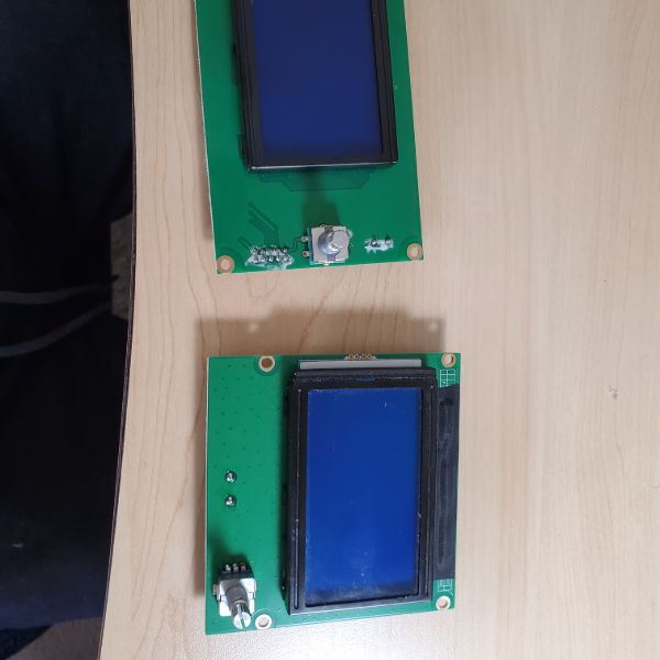
LCD Issues
One immediate issue is that the ribbon cable powering the LCD is clearly too short. I’m worried I’ll have to buy an extender or solder two ribbon cables together to make a longer one.
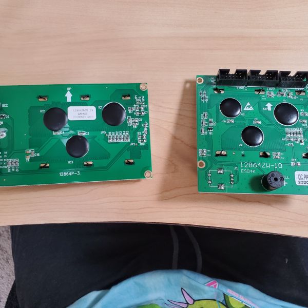
I also noticed that the LCD Screen I ordered is a 12V version. I’m hoping that isn’t an issue, since my board is 24V. I may have to use a buck converter, I’m really hoping not. I should check the pinout on the board, and on the Screen itself.
The LCD Will also not fit into the original front plate, obviously. I’m not sure where to position the new screen when it arrives.
I think it would be worthwhile to Print an enclosure like the one Jake’s has for the LCD display and simply mount it on top of the angled front surface the old LCD was in. It’s not elegant, but it’s pretty much the most elegant thing I can do without separating the controller from the main hull and making a second body.
Either way, I’ll probably have to drill some holes into the hull. On the bright side, the ribbon cable can just run right through the old screen hole
There’s a sticker on mine that says 5V so who knows. Hopefully it’s plug and play. Worst case I toast it on arrival and have to borrow Jake’s for another few days while I order a new one. That can be avoided via Datasheet checks though.
Another issue is that it’s pointless to put a mesh cable sleeve on the X-Axis Endstop because 1. It’s running through the aluminum channels and needs to be as frictionless as possible 2. It cannot be fixed at any point, since it needs to pull and drag as the Z axis moves up and down
With the current cable management, it looks like I lose about 5mm of Y range, since the cables are shorter now. It’s probably worth my time to lower the bed size in firmware so the motor doesn’t yank the bed while it’s running a lot of heater current…
After plugging it in, it looks like the motor doesn’t have any issues. down to 5mm remaining it has some amount of tension, but it doesn’t seem to hold anything back
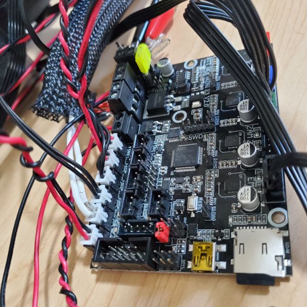
Looks like I accidentally played the extruder motor into the Z-B slot, so the Z and the extruder move together creating a clicking noise
After plugging the extruder motor into the correct slot, I still couldn’t turn it using Move Axis. I was pretty sure this was just a firmware issue refusing the move the motor while the extruder is cold, and I confirmed that the motor is still good by swapping E and X and moving X. So it’s safe to say that everything is working as intended now, and the printer is looking much, much cleaner.
At the moment, there’s not much else to do but wait for the thermistor to show up, so it’s time to clean up.
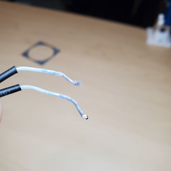
When the Thermistor gets here, I’m probably going to end up crimping its wires myself so I don’t have to deal with the stock 1 meter cable. I’d rather just use the one I already made.
New Thermistor Upgrades
The new thermistor worked out of the box. It had a 1m cable, so i cut it and used the extension cable that I already made myself prior. Mounting it had some issues because there’s some warping on the mounting plate that I printed. So I could only use one screw and made sure that one was tight, fixing it to the fan shroud
On top of that, I also found out that my z axis steps/mm were off, the prints were coming out at 50% of the height they should’ve been, so I doubled it from 400-800 in the firmware
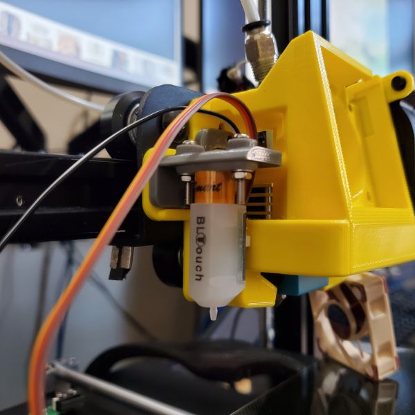
After I installed the BL Touch, I had to remount it a couple times with different numbers of bolts in order to space it properly with respect to the nozzle.
I also found a bug where the prints are coming out mirrored. I think it has something to do with the fact that my Y axis endstop is in the back instead of the front of the range, with respect to the front of the printer.
The new LCD screen works fine and I’m good to return Jake’s LCD. I’m just waiting to do so until I print a case for the new one.
After enabling BL Touch in the firmware, I also had to do some trial and error to make sure the printer had the right offsets for it. I had some issues where it dug into the bed, or started printing in the air. But after some cursory calibration it’s printing fine.
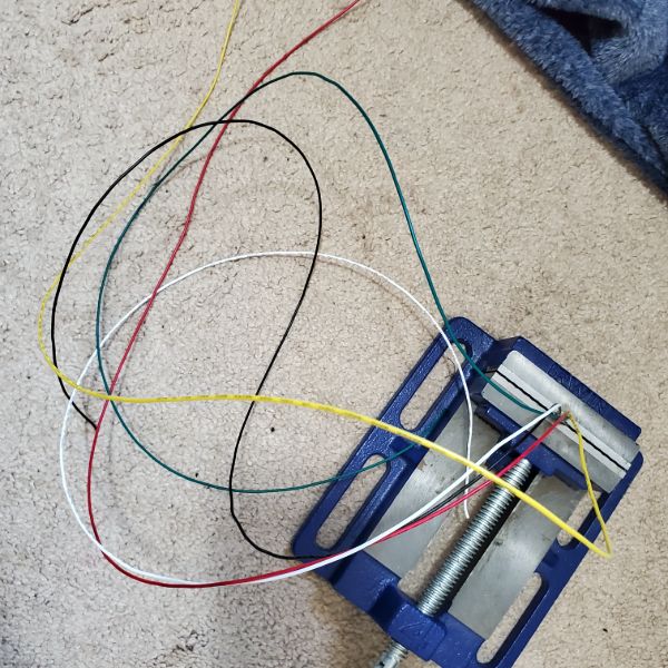
I had to create a 5 cord cable bundle for the BL Touch to go back to the mobo, which was a new process, but I’m getting really handy with the crimping kit, and had no dud wires, which was nice.
Another issue I’m having is when I print from Cura, it drops a purge line dead center in the middle of the bed. I’m not sure why, but it’s pretty cringe.
I definitely need to flip the Y-axis or something in the printer’s firmware. And I think I’ll need some fundamental overview of how G-Code works before I can comfortably say I know how this thing works.
First Calibration Cube
Results
X
19.99 – 20.00
Y
19.90 – 19.92
Z
20.00 – 20.02
It looks like the only thing I really need to change is to increase the Y steps/mm by about 0.5%.
My objectives from here are to calibrate the printer using Teaching Tech’s guide throughout the week. And then print a calibration cube that’s about as perfect as I can get it, and then move onto the Clearance Castle.
After that, I’m going to buy some more PLA, finish the FreeCAD tutorials, and then model and print out a scale replica of the Megadesk, and that will conclude the 3D Printer deep dive.
LCD Display Case
I printed a LCD case, but it was mirrored, so I mirrored it. But then I noticed that it doesn’t fit. So I thought to edit the STL. So now I need to figure out if and how to import and edit an STL file in FreeCAD
Watched a tutorial, moving forward
Filled in original hole
Adding new hole, around 10 mm down, 15 mm over, at least 8 mm diameter
Did a first layer print. Holes were slightly misaligned. Will expand circle diameter and reprint after calibration
GCode
Learn G-Code for 3D Printing
https://youtu.be/2TByiMNduss
https://marlinfw.org/meta/gcode/
Documentation on GCode Commands
Most 3D Printer GCode files have a signature comment at the top, and the printer settings commented at the bottom
G – Prepatory Commands
G0 & G1 – Linear Movement
G1 X23 Y56 Z1 E0.5 F1000
Linear Movement to XYZ Position (23,56,1) while Extruding 0.5 at a Feed Rate of 1000
The feedrate will persist until changed
G0 for rapid moves, precision not needed, traveling
G1 for precision movements, extrusion moves
These are basically the same in modern 3D Printers but the convention remains
G90 & G91 – Positioning Mode
G90 – Absolute Positioning
G91 – Relative Positioning
Either move to 50,50, or change position by 50,50
Most GCode movements in 3D Printers are absolute positioning
One example:
G91
G0 Z10
Lift Print head by 10mm
G90
G0 X230
G28 – Homing
Your machine doesn’t know where it’s at when you turn it on. The steppers don’t keep track of that.
G28 initiates homing routine
You can specify specific axes
G28
Does All
G28 X Y
G28 Z
G29 – Bed Leveling
Usually comes after G28
Activates Bed Leveling Probing Routine
G92 – Set Current Position
G92 X0 Y0 Z0 will set the current position to be the origin of the coordinate system
You can also G92 E0
M – Miscellaneous Commands
M82 & M83 – Extruder Positioning Mode
M82 – Absolute Positioning
M83 – Relative Positioning
Mostly a preference of the slicer software
Prusa uses relative, Cura uses absolute
M104 & M109 – Set Nozzle Temperature
M104 S210
Set Nozzle Temperature AND CONTINUE reading GCode while heating
M109 S210
Set Nozzle Temperature AND CEASE reading GCode until done heating
M140 & M190 – Set Bed Temperature
M140 S65
Set Bed Temperature AND CONTINUE
M190 S65
Set Bed Temperature AND WAIT
4 means go
9 means wait
M106 & M107 – Set Fan Speed
M106 S255
Set fan speed to 100%
M106 S128
Set fan speed to 50%
M106 S0
Turn fan off
M107
Turn fan off
M84 – Disable Stepper Motors
M84 X Y
Disable Stepper Motors for just those axis
Teaching Tech 3D Printer Calibration
Settings:
Layer height 0.2
Wall thickness 0.4
Print Temp 230/50
Flow 90%
Print speed 60mm/s
Retraction 3mm
Retraction speed 30mm/s
Prime speed 40 mm/s
Z Hop 0.4
Print Cooling 100%
Print Acceleration 1400
Junction Deviation 0.21
Linear Advance K=0.55
X range: 210mm
Y range: 230mm
Probe Offset
X: -43mm
Y: -10mm
Z: -1.70mm (many passes on this)
Intro
Zupfe – GCode Viewer
https://zupfe.velor.ca/
Web based G Code Viewer
G Code Reference Manual on Marlinfw
https://marlinfw.org/meta/gcode/
Frame Check
V Rollers
The V Rollers on the frame sides seem to be just fine, but on the print head, the new ender 3 backplate I ordered seems to have just a little bit of wobble/give as though it weren’t fastened properly. I’ve tightened everything I can, and the friction on the wheels themselves doesn’t seem to equalize or change in a significant way. either way, when the printer moves them, the top two wheels turn and the bottom stays fixed, and the slack doesn’t end up creating any wobble, some I’m hoping this isn’t a big issue
PID Autotune
Installing Pronterface
https://www.pronterface.com/
New Values to add to firmware
#define DEFAULT_Kp 82.31
#define DEFAULT_Ki 15.32
#define DEFAULT_Kd 110.54
PID Autotune Log
SENDING:M303 E0 S215 U1
//action:notification PID Autotune
PID Autotune start
bias: 231 d: 23 min: 209.88 max: 216.04
bias: 219 d: 35 min: 214.14 max: 216.82 Ku: 33.23 Tu: 40.73
Classic PID
Kp: 19.94 Ki: 0.98 Kd: 101.50
bias: 207 d: 47 min: 214.88 max: 216.41 Ku: 78.56 Tu: 16.20
Classic PID
Kp: 47.14 Ki: 5.82 Kd: 95.43
bias: 207 d: 47 min: 214.49 max: 215.36 Ku: 137.19 Tu: 10.74
Classic PID
Kp: 82.31 Ki: 15.32 Kd: 110.54
PID Autotune finished! Put the last Kp, Ki and Kd constants from below into Configuration.h
#define DEFAULT_Kp 82.31
#define DEFAULT_Ki 15.32
#define DEFAULT_Kd 110.54
//action:notification Kurosaki 4 Ready.
ESteps Calibration
E Steps Calibration was already pretty good. 93.00 -> 93.46
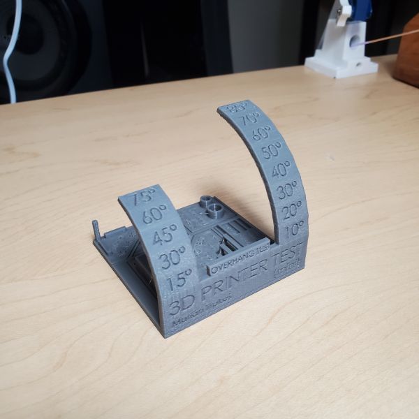
First Layer
This required a lot of testing. I figured out that the GCode generator on the website wasn’t registering as a Print to the printer, even though Cura thought it was. I had to adjust the Z Probe offset repeatedly and this ate up a good chunk of time today. I finally settled on the closest value that resulted in test squares that were completely connected. All further values resulted in squares that had spaces between the diagonals.
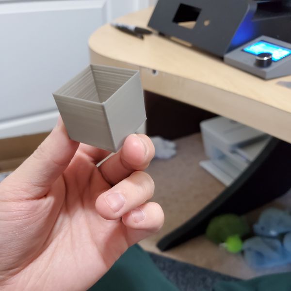
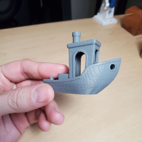
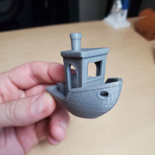
Baseline Print
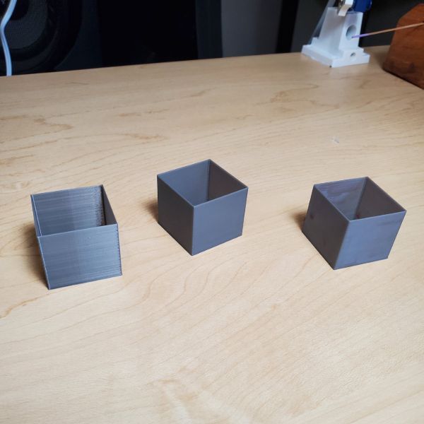
Calibration Cube. I already have one from before, but I’ll have to print another later, once the calipers arrive
Slicer Flow Calibration
I printed the box, but Jake won’t let me use his calipers. Mine will arrive tomorrow, so I can check flow rate then.
Calipers Arrived
All box wall thicknesses are 0.37-0.38mm
This means that the new flow rate should be 105.26%
That was too much. Since I changed temp and retraction since then, this test needed to be reran, twice. I settled on a number about 90% Flow Rate and that gave me good results with my current temperature and retraction settings.
Stepper Motor Current
No need to do this, the steppers never get hot
Temperature Tuning
I tried running at temps around 190 and 195 and even 200, but the extruder is unable to force the filament through the hotend at those temps. The all metal hotend requires a higher temperature.
Running a test with a minimum temperature of 210C seems to be the lowest temperature at which extrusions continues seamlessly
0.4mm nozzle, 0.2mm layer height
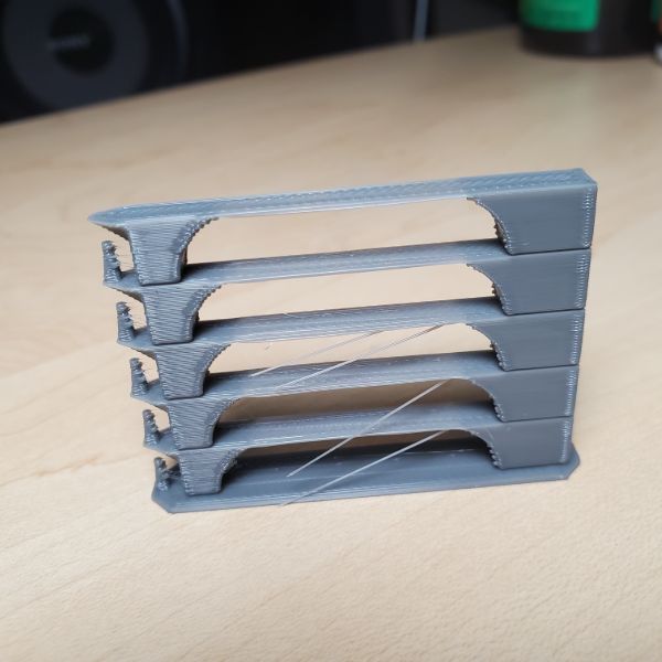
Inputs
230 looks the best. doing all prints on 230 from now on
This is probably the best thing I’ve ever printed lol
230 has the strongest bridge and the least stringing
for the spikes, 220 > 215. 220,225,230 are all about the same
Used a Retraction distance of 2mm, retraction speed 40. Feedrate 40
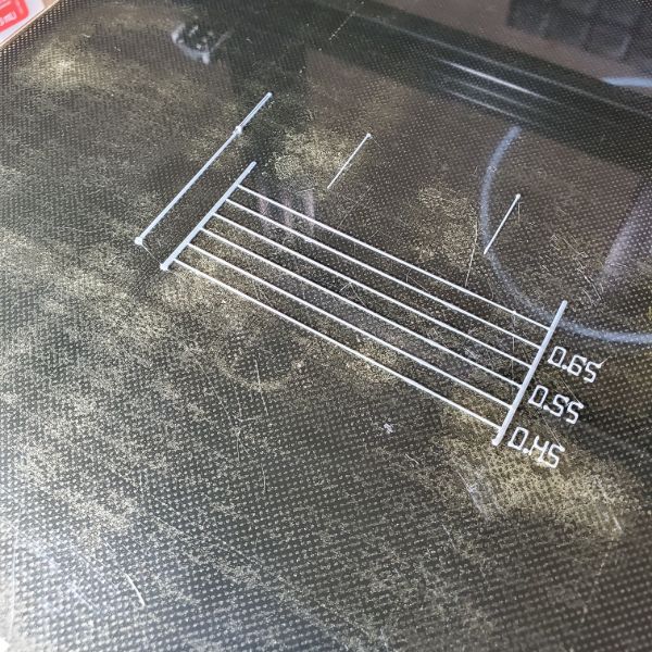
Retraction Tuning
Print 1
Looks like everything 2 and above is great
3 Seems to be the best
Needs more tuning to make sure stringing is minimized.
The print only takes about 10 minutes either way so this should be easy to iterate many times
Print 2
It looks like the first 2 are good
30 and 35 are the only two settings with zero stringing
Moving forward with 30, since the bumps are smaller on 30 too
Print 3
3.0 is definitely the best.
Print 4
This time checking if Z-Hop is helpful
I only went out of order because I know Z Hop, but don’t know much about the restart distance/speed.
Once I have set values for all 5 variables, I’m going to compile the settings, and save a profile
I still need to check flow rate and print another calibration cube
I’m also going to print another retraction tower after fully tuned but with the part cooling fan off to see what difference it makes
ZHop 0.4 is the smoothest. The little nubs at the edge of the print are the smallest and smoothest
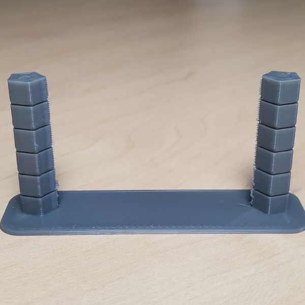
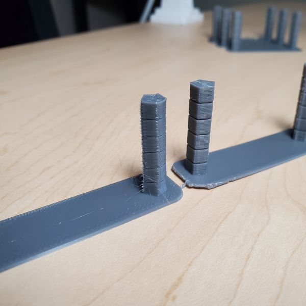
Acceleration Tuning
The F in GCode lines is for feedrate and is measured in mm/min
so G1 S50 Y60 E3.7 F3000
The F3000 is 3000mm/min, or 50mm/sec
Printed the piece about 5 times. Settled on Junction Deviation 0.21, and Accel of 1400
Linear Advance
Enabled Linear Advance, only took about 3-4 passes. Pretty simple stuff
XYZ Steps Calibration
Speed Tuning
Firmware Dive
Custom Bootscreen
Burned about 2 hours on this. There’s an option for Custom bootscreens that load from a _Bootscreen.h in the root /Marlin folder. But I couldn’t get it to work. for a while after generating the 128×64 monochrome bitmap in C array form
I figured out I need to uncomment BOTH the OEM Marlin Bootscreen AND the Custom Bootscreen for the custom to show, but then they. both show.
I can’t really figure a way around that so I’m dropping it for now
Axis Inversion Issue
Testing to see if I need to invert Y or X or both. There’s a motor direction inversion in Config.h around line 1200 but I’m worried it’s not what I think it is
I told it to print in the 0,0 corner, and it printed in the X MIN/Y MAX corner, so I believe Y needs to be mirrored
Inverting Y movement, Setting endstop to LOW end, and defining as a MIN endstop AND inverting endstop logic for y min endstop
I think that just creates the same issue but backwards
Flipping everything did fix the issue and now the printer knows that the bottom left is the 0,0 corner. So that fixed the mirroring Issue
Purge Line in Center issue
The new auto-leveler causes the AutoHome all axis command to finish in the dead center of the board. The purge line calls for only x axis movements in tandem with the extrusion
I fixed this issue by adding a line of GCode in between the homing/leveling phase, and the purge line phase, where the printer heads over to the bottom of the y-axis, then runs the purge line. worked perfectly
New Start GCODE
; — START GCODE —
G21 ;set units to millimetres
G90 ;set to absolute positioning
M106 S0 ;set fan speed to zero (turned off)
G28 ;home all axis
M420 S1 ;turn on mesh bed levelling if enabled in firmware
G92 E0 ;zero the extruded length
G1 Z1 F1000 ;move up slightly
G1 Y5.0
G1 X60.0 Z0 E9.0 F1000.0;intro line
G1 X100.0 E21.5 F1000.0 ;continue line
G92 E0 ;zero the extruded length again
; — end of START GCODE —
Calibration
Z range: 200mm
lost X range on left (low): 20mm
X: 0-20mm inaccessible
X range: 210mm
Y range: 230mm
Probe Offset
X: -43mm
Y: -10mm
Z: -1.70mm (many passes on this)
Thermal Shrinkage
https://youtu.be/0dFThbwAx2Y
Generally, each filament will have a different Thermal Shrinkage %
The example in this case for ABS+ was 0.5%
The result is that whenever you slice something, you should apply a uniform scaling to 100.5% in every dimension, so that the print comes out Dimensionally Accurate
https://3dinsider.com/pla-shrinkage/
PLA Shrinks about 0.8% – 3%, average around 2%. This depends on the specific context for your printer, so it needs to be measured manually
FreeCAD Tutorials
Casino Dice Tutorial
https://youtu.be/uBKhBwSP_iM?list=PL6fZ68Cq3L8k0JhxnIVjZQN26cn9idJrj
After designing a part in the “Part” view, you can’t just switch to Part Design and start sketching on it.
First, you have to switch to Part Design, then select the Part, and then click the stairs icon to “Create a new body and make it active”
While creating a sketch, if you want to declare some of the geometry within the sketch as “Support” or “supplementary” and have it not influence any pocket or pad type extrusion operations, you have to convert the lines into “Construction Mode”
Once this is done, the Construction geometry will still exist within the sketch, and additional non-Construction geometry can reference it for position and dimension, but it will not appear in the final render. Construction Lines are Blue
16mm square for rigging
3mm radius circle for dots
Opposite sides add to 7
Pocket 0.1mm
Bearing Bracket Tutorial
https://youtu.be/cRFsW_FhyP4?list=PL6fZ68Cq3L8k0JhxnIVjZQN26cn9idJrj
Use case for the tangent constraint tool: running circles off the rim
When Sketching, You can usually only reference the axes themselves, and not any edges on the sketch
That’s what this tool is for. You can use it to select another edge and bring it into the sketch for framing/rigging/reference
Fork Bearing Tutorial
https://youtu.be/0-WmlAh5dhQ?list=PL6fZ68Cq3L8k0JhxnIVjZQN26cn9idJrj
It’s recommended that you write down a list of keyboard shortcuts and keep them near your computer to improve your workflow
Example, Reset View – 0,V,F
Isometric View
0
Fit All
V, F
The Part toolbar has measurement options that allow you to check and measure lengths of the 3D model as is.
You can copy paste Sketches. You just copy it, and then de-select everything, click empty 3D space, and then Edit -> Paste. This will drop the sketch into the body list.
However, you need to drag the sketch into the body so that it’s assigned to that body. Sketches need to belong to a body.
From there you can make whatever small adjustments you need to make and then proceed. For this reason though, it’s generally better to have your sketches anchored onto Axial Planes instead of elements of the existing body, as that will severly complicate the process of copy-pasting dependent sketches
If you want to clone a sketch onto a different plane (rather than just creating a new instance on the same plane), you have to go to the sketch toolbar, and then dropdown Sketch > Reorient Sketch
If you refer a link to external geometry onto a circle, you get access to the center point of that circle
FreeCAD Macros
https://wiki.freecadweb.org/Macros
Propeller
https://youtu.be/petFK9wcxFY?list=PL6fZ68Cq3L8k0JhxnIVjZQN26cn9idJrj
It is better to have overlapping solids if you plan on using a boolean fusion
Inner Threads
https://youtu.be/Y5b1FUEfAFw?list=PL6fZ68Cq3L8k0JhxnIVjZQN26cn9idJrj
Since the part design workbench treats every sketch and extrusion as a subsequent step on a single body, the boolean combinations in the part workbench won’t work very well unless you make a point to put the different bodies into different bodies
Importing and Editing STL Files in FreeCAD
https://youtu.be/dr1qtaURrvI
Summary
Part Workbench
Import STL
Convert Mesh to Object
Refine Object
Convert Object to Solid
Switch to Part Design Workbench
Create Body
Add Solid to Body
Proceed with Edits
Steps
1
Create a new FreeCAD Document
2
File > Import > .STL file
3
FreeCAD imports the STL file as a Mesh. Convert the Mesh to an Object that can be worked on by switching to the Part workbench, selecting the mesh, and running Part > Create Shape from Mesh. After running this, delete the original mesh
When this happens, it has to “sew” together many polygons at a specific tolerance to form the object. The highest precision allowed is 0.01 mm
This creates a high poly render of the mesh as an editable object
4
In order to get rid of redundant polygons, select the new Object model and run Part > Create a Copy > Refine Shape. This will simplify the surface dramatically. After running this, delete the original object
5
Now that the object has been refined, all that’s left is to run Part > Convert to Solid. This will create a copy of the object that can function as a solid. Delete the original, Non-Solid
6
Switch back to Part Design workbench, then create an empty Body in the project, and add the newly converted solid to that body as a Base Feature. From there, you can sketch, add pockets and extrusions, etc. And should be fully functional for edits