Project Summary (Technical Overview):
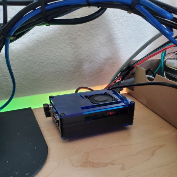
Breadnet is a local-network IoT server hosted on a Raspberry Pi4. It’s running whatever Raspbian OS is recommended, and hosts a Node-RED and Mosquitto server, and doesn’t do much else. Both Node-RED and the MQTT are insecure, because I can’t be bothered to SSL something that maybe 5 people both know about AND understand enough to point out that it’s insecure. It’s also not port-forwarded/open to the web so.
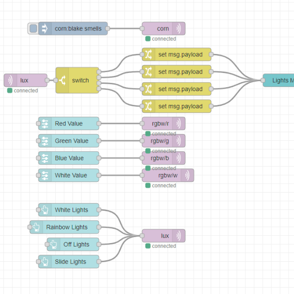
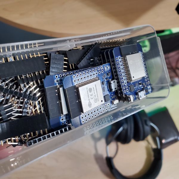
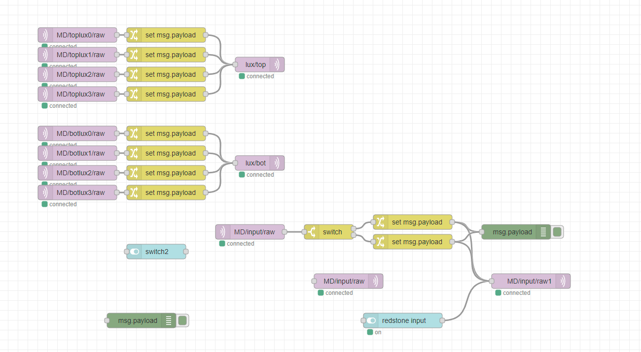
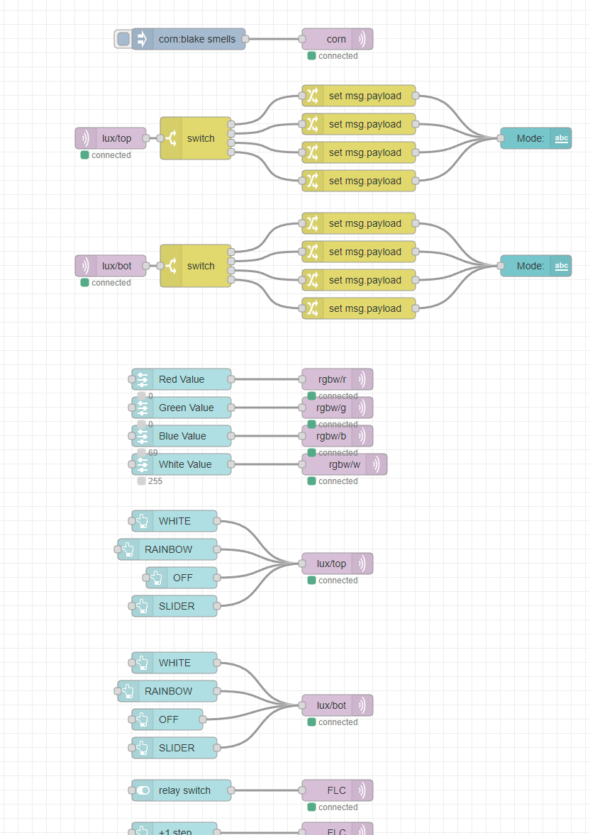
The Node-RED is the backbone of my IoT network, MQTT is the communications protocol, and I use ESP32 boards as the Module/Clients. I’ve got a pile of 10-20 ESP32 boards that I use for different projects, and connect them all back to Breadnet so I can take full advantage of the interconnectivity Node-RED offers.
I’ve written up a Generic Breadnet Module script that I use as the basis for every additional module I add to the network. I mostly just change the topics and add whatever functions are necessary to get the project up and running. This saves a TON of overhead and means I can add something new to my network basically less than an hour after conceiving of the idea to, so long as the code is something simple like reporting sensor data or flipping a switch. The nature of this system is that the Node-RED can arbitrarily define the interaction logic between all devices connected to it, which means I can do things like, flip a switch on a minecraft server and cause my garage to open, and then the garage’s open/close state can be reflected by one of the LEDs on my desk lights. That type of thing.
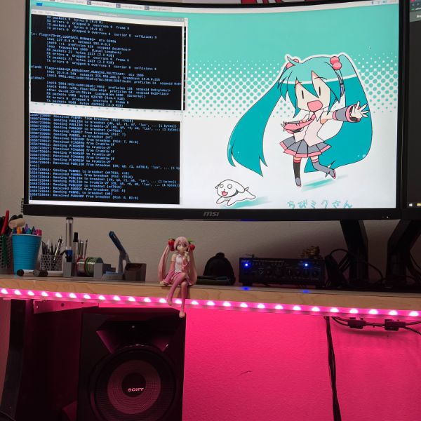
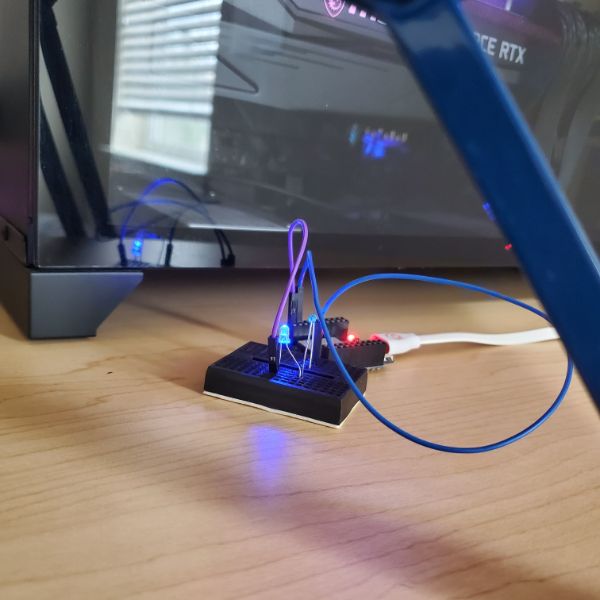
Final Project Pics
Project Summary (Personal Overview):
This project is something I’ve set up about 2 times before, but this is the first time I’ve formalized the process and basically set up SOP’s for connecting additional modules. Last time I built this type of network I didn’t take any notes on how I set it up, and I definitely didn’t analyze the code I used on the ESP8266’s in detail. This time I made sure to create the most barebones, generic module script for the ESP32 and take thorough notes on everything so this doesn’t get lost.
I still honestly don’t know enough JSON to make full use of Node-RED but I generally adapt to need anyway. I’m happy to have the process of connecting to Breadnet locked down. I’ve thought about creating a docker image so that I can just quickload the entire network onto any Pi/VM I want. This whole thing can also be hosted over AWS, but that’s lame.
Project Cost Breakdown: $150
Just a Raspberry Pi4, and some ESP32 modules
Project Timeline Breakdown: 1.5 Months
It’s really not that complex, just set up Raspbian, install Mosquitto, Node-RED, configure both, and then write a generic script for an ESP32 module. The whole thing could be set up in about an hour if I use the same script.
Project Gallery
Project Notes
2022-H
Breadnet
Resources
https://wiki.beyondlogic.org/index.php?title=Main_Page
https://docs.espressif.com/projects/esp-idf/en/latest/esp32/index.html#
https://pypi.org/project/paho-mqtt/
https://www.npmjs.com/package/paho-mqtt
https://mntolia.com/mqtt-python-with-paho-mqtt-client/
https://mosquitto.org/documentation/
Next Steps
Connect ESP32 to WiFi
https://www.dfrobot.com/blog-948.html
Connect an ESP32 to the mqtt and run a brief blink every time it receives a message
Brain is gassed out. Picking MQTT tomorrow
Configure the ESP32 to only run a blink if the string matches the expectation
Configure the ESP32 to drive Neopixels
Insert the ESP32 into the lightsbox
Set up a Node-RED flow to ping the ESP32 to toggle all the pixels on or off
from there, move onto priority interrupts
Notes
Time to set up Breadnet again!
I’m thinking this time I’ll put it next to the lightsbox, so it can take the USB tap that controls mouse and keyboard. I’ve got the miniHDMI that I can plug into the left monitor. That way I can switch to the Pi at a moments notice, just like my work laptop
I’m pretty sure it’s still on HASS, so I’ll have to pull out the SD card and flash it for linux first
was rotom, then hutao, now breadboy
If I’m gonna make anything useful, I’m probably going to have to take time and dive into each element separately
MQTT
Mosquitto
Node-RED
JSON
ESP32
SK6812
Setup
Pi Flash
Set up a miku wallpaper, made sure everything was up to date
Installed TreeSheets on the Pi, new move!
Unfortunately, I can’t get dropbox on the Pi because it uses an ARM processor which dropbox app doesn’t support, so I can’t sync the lab notebook onto the pi without issue
Installed Node-RED and Mosquitto and set them both up
Defined users for eein and angel for node red
Mosquitto now requires a .conf file to allow any external connections, so I had to write that.
MQTT – Mosquitto
requires a .conf
This will have to get modified over time to increase sophistication and security
MQTT Server (local)
10.0.0.25:1616
Mosquitto version 2.0.11 using MQTT v5
The basic format of a MQTT message
I converted msg.payload into a string and then printed it. It looks like every MQTT message comes in the format
b’message’
Where there’s a b at the front, and then quotations around the message itself
Node-RED
Now has a “Projects” functionality that can sync with github
No Idea what’s going on there
Node-RED can also connect with the new MQTT v5
Python
Using sample code from the paho.mqtt library to connect to the server
Ran in VS Code. Python IDLE didn’t work right away, and it’s also just not as usable
Here’s the script:
import paho.mqtt.client as mqtt
# The callback for when the client receives a CONNACK response from the server.
def on_connect(client, userdata, flags, rc):
print(“Connected with result code “+str(rc))
# Subscribing in on_connect() means that if we lose the connection and
# reconnect then subscriptions will be renewed.
client.subscribe(“corn”)
# The callback for when a PUBLISH message is received from the server.
def on_message(client, userdata, msg):
message = str(msg.payload)
print(msg.topic+”:::”+message)
print(len(message))
print(message[0])
client = mqtt.Client(client_id=”vscode”)
client.on_connect = on_connect
client.on_message = on_message
client.connect(“10.0.0.25”, 1616, 60)
# Blocking call that processes network traffic, dispatches callbacks and
# handles reconnecting.
# Other loop*() functions are available that give a threaded interface and a
# manual interface.
client.loop_forever()
MQTT Dash (mobile)
connects just fine
MQTTX – Desktop monitoring
Can submit JSON payloads
Research
Serial Communication (UART,SPI,I2C,USB)
USB
How does it work
USB2.0 cable has 4 wires
Power 5V
Ground
+Data
-Data
Differential Pair to ensure signal integrity
Master has many responsbilities
Hardware
Detecting USB Connections
Providing Electrical Power
Controlling Data Transfer
Software
Handling Connectivity
Configuring multiple USB devices
Running the devices’ drivers
Managing Power and Bandwidth
USB TYPE A is the MASTER’s PLUG
This is what connects to the host
This is where the power and data come from
All other USB types are SLAVE PLUGs
They do not send power nor data
You have never seen an A-A USB cable
USBs are easy from the user perspective
USB can be very difficult from a Developer Perspective
Terms
USB
Host – Master
Device – Only transmits when the host has an outstanding transaction
OTG – on the go, indicates some limited Host Functionality
Hub – Expands the host’s ports, and acts as a signal repeater
Frame – Time division of the USB bus. Is the basis for all USB communication
Packet – Bundle of data for transmission
A Frame is made up of multiple Packets
Enumeration – The handshake process that occurs every time a device is connected to a host.
The windows USB noise indicates the START of the enumeration process.
The device showing up in device manager with a success status indicates the END of the enumeration process
Descriptor – a structure in the connected device’s firmware that describes
All the capabilities of the device
What interfaces it supports
What type of device it is
etc.
Structure
HOST
HOST’s ROOT HUB
DEVICE
DEVICE
HOST’s extra HUB
DEVICE
DEVICE
Bus Organization
Since the host is the master of all traffic, it’s the reference point
IN TRANFERS – from the device INTO the host
OUT TRANSFERS – from the host OUT TO the device
Speeds
USB Types have different speeds. These speeds determine Frame Timing in data transfer
Low Speed
USB 1.0
1.5 Mbps
Full Speed
USB 1.1
12 Mbps
High Speed
USB 2.0
480 Mbps
NROOOM
USB 3.0
5 Gbps
Transfer Types
Control Signals
Best effort delivery
Used for transfer command and status operations like enumeration
Bulk
Mass Storage Devices
Guaranteed Data Delivery
High Data Throughput
No Latency Promise – Lowest Bus Priority
Interrupt
Human Interface Devices HIDs
Mouse and Keyboard
Low data throughput
64 bytes per millisecond
Guaranteed Latency
HIGHEST bus priority
Isochronous
Guaranteed Latency
High Data Throughput
No Guaranteed Delivery – packets can be lost without consequence
Frames
Frames provide a data structure for the bus Below is an example frame with 2 interrupt devices and 2 bulk devices
1 millisecond frame
Start of Frame – SOF
Control or Data Packets
INTERRUPT 1
INTERRUPT 2
Control Packet
BULK 1
BULK 1
BULK 1
BULK 2
BULK 2
BULK 2
BULK 2
BULK 2
UNUSED
UNUSED
UNUSED
UNUSED
If a device isn’t ready to talk when the master addresses it, it can lose it’s slot in the frame. Stay on the bus
Certification
USB Logo certification refers to certified hardware.
Ran by USB.org
USB Device Drivers can also be certified
Tips
UART is usually a steady stream of information
A CP210x device can convert USB to UART, but the timing might change
The throughput of each device may be affected if there are too many Bulk or Isochronous types connected to one host
If an Interrupt device misses its slot because it wasn’t ready when the host called for it, it will have to wait until next frame
USB Topology
USB 3.0
Dual bus architecture
Consists of a 2.0 and a 3.0 host, with a bus for each, simultaneously
USB 3.0 has the same 5V Supply and Ground return
So a USB3.0 hub can take both 2.0 and 3.0 devices
But the big difference, is it has three fully differential data pairs
The original D+/- data line
and then 2 Superspeed channels
SSTx+
SSTx-
SSRx+
SSRx-
in 3.0 Hubs route packets only to the corresponding device
3.0 Hubs also help with power management
Host
There can only ever be one Host on a given USB bus
All hosts must have a root hub integrated within the system
The host is the brains of the hub system, and has a lot of responsibility
Responsible for transaction initiation and flow control
The ON THE GO standard allows slave devices to initiate transactions
Devices
devices are responsible for maintaining protocol and timing. sending and receiving packets, etc.
Compound Device
combo of a hub and a device
USB Power Class
Bus-Powered
draws all operational power from the upstream facing port
Defaults to 100mA current draw
Can Negotiate with the host for up to 500mA
Hubs are required to provide 100mA to all downstream ports as protocol
Self-Powered
Draws its power from a non-bus supply
Can still draw up to 100mA from the upstream port
3.0
supports all USB2.0 power classes
Increases in power limits
50% in default
150mA
80% in negotiated
900mA
New Low Power States
Idle, Sleep, and Suspend
Lower Power Overall
USB Address
1 host, many slave addresses
There are 127 Unique addresses per USB host
Host is responsible for assignment. The devices do not have addresses by default and must wait to be assigned one by the host
USB Endpoints
In/Out directionality is always from the Host’s point of view
Endpoints are a logical structure repsenting the source and sink of data transactions between host and device
IN Endpoints and OUT Endpoints
Devices can support any combination of IO
ENDPOINT_0 In and Out are reserved for control signals like enumeration in all devices
Pipes
a direct logical connection between a host and one or more endpoints
Message Pipe
Stream Pipe
Enumeration
Process by which host interrogates all devices for their attributes and assigns them an address
Enumeration must be complete before the host can access thed evice
USB Requests
Requests define the mechanisms for host/device communication
Standard Requests are agnostic to actual device functionality
https://beyondlogic.org/usbnutshell/usb6.shtml#StandardDeviceRequests
There are a list of USB Standard Device Requests
bmRequestType bRequest wValue wIndex wLength Data
1000 0000b GET_STATUS (0x00) Zero Zero Two Device Status
0000 0000b CLEAR_FEATURE (0x01) Feature Selector Zero Zero None
0000 0000b SET_FEATURE (0x03) Feature Selector Zero Zero None
0000 0000b SET_ADDRESS (0x05) Device Address Zero Zero None
1000 0000b GET_DESCRIPTOR (0x06) Descriptor Type & Index Zero or Language ID Descriptor Length Descriptor
0000 0000b SET_DESCRIPTOR (0x07) Descriptor Type & Index Zero or Language ID Descriptor Length Descriptor
1000 0000b GET_CONFIGURATION (0x08) Zero Zero 1 Configuration Value
0000 0000b SET_CONFIGURATION (0x09) Configuration Value Zero Zero None
USB Packets
Transfer types are defined by the specific sequence of packets
Four types of packets
Token Packet
Used to describe what type of activity the host is requested
Data Packet
Contains the non-protocol payload, or may just be empty
Handshake Packet
Similar to acknowledge in I2c
Special Packet
Rarely used, special cases only
USB Packet Fields
Sync
Packet Identifier
Address
Endpoint
Cyclic Redundancy Check
End of Packet
USB Device Classes
group of devices with similar attributes or services
Each class has it’s own unique requirements
eg. Audio Class: Speaker, Microphone, etc.
USB Device Classes are defined external to the official USB Documentation
USB Schematic Considerations
The speed of the differential pairs are determined by the pullup resistance on the D+/- lines
Low Speed
1.5k R from VBus to D-
Full Speed
1.5k R from VBUS to D+
High Speed
1.5k R from VBUS to D+*
* High Speed device must initialize as Full Speed then get the host to acknowledge it as High Speed
USB 3.0 super speed devices must have the ability to dynamically attach/detach the pullup resistors
OTG devices have a 5th, ID pin
determined by resistance, not logic level
leave floating for device
tie directly to ground <10R trace for host mode
USB Layout Considerations
Typical high speed ringing, distortion, mismatched impedance
All normal signal integrity stuff for Superspeed USB functionality
Constant trace impedance is key for signal integrity
Some real tips on signal integrity tracing here:
https://youtu.be/_n1zaNr_5-Y?t=1458
Intel provides a Intel High Speed USB Platform Design Guidelines
USB Device Offerings
Dedicated USB Controller chips, with dedicated USB serial interface engines
8bit
TUSB3200
16bit
32bit
Universal Serial Bus Explained
Further Reading: USB COMPLETE – JAN AXELSON
http://janaxelson.com/usbc.htm
https://youtu.be/_n1zaNr_5-Y
https://youtu.be/5S6ZPmtPzRA
https://youtu.be/cgKRQsGSk-c
Design started in ’93
Computers used to SUCK
Most PCs had 2 Serial Ports (VGA Style)
The 7 Tech Companies Conspiared to make a USB
DEC
NEC
IBM
COMPAQ
Intel
Nortel
Microsoft
Objective
Universal
Fast
Multifunctional
1995 – USB 1.0
Plug and play, hotswappable, super easy
If the PC doesn’t recognize the device, it will install a driver for it
FTDI
FUTURE TECHNOLOGY DEVICES INTERNATIONAL
A Scottish Semiconductor Device Company specializing in Universal Serial Bus Technology
They make adapters that convert USB type data to UART type data
6 pins: 2 power (VCC, GND) and 4 data (CTS, TX, RX, DTR)
Transmit, Receive, Data Line Ready, Clear to Receive
Three Types of Serial Communication Protocols:
https://youtu.be/IyGwvGzrqp8
UART
Asynchronous – doesn’t use a clock
UART
Synchronous – uses a clock pulse to time pulses containing data
Asynchronous – doesn’t use a clock
One wire for Tx/Rx, One wire for Ground.
How does it know when to start and stop?
The transmitter and receiver need to be on the same page, configured in the same way
This means they should both be expecting the same Tranmission Speed (baudrate), the same Data Length, and the same START and STOP bits
UART usually uses a 1-cycle LOW pulse to indicate the start bit. before and after data, the signal is held at HIGH
UART is limited in length to about 15m
RS-232 and CAM BUS can travel long distances
UART has an acknowledge pin, but I2C and SPI don’t. This means I2C and SPI can transmit data even if there isn’t a receiver/slave connected
RS-232
RS-232 is just another type of UART
Every computer uses UART
On a UART Chip, you might see these pins that act as flags
DTR – Data Terminal Ready
CTS – Clear to Receive
Most devices have both Tx and Rx so they can both send and receive. But if data is only going one way you only need one wire
I2C
Inter-Integrated Circuit
Synchronous type, requires a clock pin
SDA – Serial Data Line
SCL – Serial Clock Line
Still need to specify the Data length and Frequency
usually up to 400Kb/s & 15-16 bits
Designates a Master Device and a Slave Device
Communication is still one-to-one, but can address different slave/receiver devices
The Master sends the Address Byte first, then the Data Byte
Only the Addressed Slave will store the Data into its buffer
I2C is limited in length to about 1m
1. I2C is Half-Duplex (not Simplex)
2. SPI is Full Duplex
3. In I2C, we can configure the peripheral to both the modes – Acknowledge and No Acknowledge
SPI
Serial Peripheral Interface
Also Synchronous
Five Wires Total
SCLK – Clock
MOSI – Master.output, Slave.input
MISO – Master.input, Slave.output
SS_ – Chip Select
Ground
Also Uses One Master and multiple Slaves
SPI requires a unique wire for each chip select on each slave. You can’t use an address bus like you can with I2C.
The consequences of this are that I2C is the simpler protocol, but SPI allows for FULL DUPLEX – meaning both the master and slave can be sending data at the same time
SPI also goes faster and consumes less power than I2C
SPI is limited in length to about 20cm
There are many more types, here’s a bigger list
SBUS
JTAG
I2C
SPI
USB
PPM
UART
CAN
MIDI
RS-232
UART
how does UART work??? (explained clearly)
https://youtu.be/V6m2skVlsQI
Universal Asynchronous Receiver/Transmitter
Two Devices communicate data both ways
Hardwire communication
3 Wires
GROUND
Tx
Transmission
Rx
Reception
Device 1’s Tx line plugs into Device 2’s Rx port
So, 1 wire for ground, and 1 wire for 1->2 communication, and 1 more wire for 2->1 communication
Transmission of data via binary signals
When you communicate a signal like 01001111, you keep the signal up at HIGH for four cycles, you don’t bring it down and back up again four times
Baudrate
bitrate
9600 Baudrate = 9600 bit/s
Receiving device checks the transmitting pin for a LOW or HIGH signal
Once every 1/9600th of a second
104uS
Serial Communication, as compared to Parallel Communication (8 wires, 1 for each bit in the byte)
More Time, or More Wires
Misc Questions
What’s the difference between Python, CircuitPython, Embedded Python, Python Embdedded, and Micropython?
How to do OTA updates on ESP32?
XOD – Visual Programming for Microcontrollers
MQTT
Mosquitto
Node-RED
JSON
ESP32
Espressif Documentation
Forum
https://esp32.com/
Github for doc
https://github.com/espressif/esp-idf/tree/5bb59b00e72f8f91eb24d8c65bf9a7ea2b8a4f5f
ESP32 Libraries
https://docs.espressif.com/projects/esp-idf/en/latest/esp32/libraries-and-frameworks/cloud-frameworks.html
Documentation
https://docs.espressif.com/projects/esp-idf/en/latest/esp32/index.html#
FAQ
https://docs.espressif.com/projects/espressif-esp-faq/en/latest/
Get Started
ESP-IDF – Espressif IT Development Framework
ESP32 is a SoC with the following features
WiFi 2.4 GHz Band
Bluetooth
Dual High Performance 32-bit LX6 CPU Cores
Ultra Low Power co-processor
Multiple Peripherals
Design
Made with 40nm tech
Designed to keep up with efficient power usage, compact design, security, high performance, and reliability
Equipment
ESP32 Board
USB Cable
Computer
List of Official ESP32 Development Boards
ESP32-DevKitC
ESP-WROVER-KIT
ESP32-PICO-KIT
ESP32-Ethernet-Kit
ESP32-DevKit-S(-R)
ESP32-PICO-KIT-1
ESP32-PICO-DevKitM-2
ESP32-DevKitM-1
List of Different ESP32 Modules (the chip itself)
ESP32-WROOM-DA
ESP32-WROOM-32E
ESP32-WROOM-32UE
ESP32-WROOM-32D
ESP32-WROOM-32U
ESP32-SOLO-1
ESP32-WROVER-E
ESP32-WROVER-IE
Each of these DevBoards has a different form factor, PCB, peripherals, etc. But use the ESP32 as it’s main chip. They’re pretty distinct in terms of size and shape
There is an ESP Product Selector
https://products.espressif.com/#/product-selector?names=
The ones I have are ESP32-DevKitC V4
The ones I have have the ESP-WROOM-32 Chip
the WROVER types are bigger
Software
ToolChain – compiles code for ESP32
Toolchain includes Python, Git, cross-compilers, CMake, and Ninja build tools
Embedded Python, OpenOCD (On Chip Debugger)
https://openocd.org/pages/documentation.html
Build tools: CMake & Ninja 0 build a full “Application” for ESP32
ESP-IDF – contains API for ESP32 and scripts to operate ToolChain
VSCode Extension for this specifically
Features
Setup, will help you to quickly install ESP-IDF and its relevant toolchain with just a few clicks.
Build, with one-click build and multi-target build, you can easily build and deploy your applications.
Flash, with both UART and JTAG flash out-of-the-box.
Monitoring, comes with a built-in terminal, you can trigger IDF Monitor Commands from within VS Code as you are used to in traditional terminals.
Debugging, with out-of-the-box hardware debugging.
GUI Menu Config, provides a simplified UI for configuring your chip.
App & Heap Tracing, provides support for collecting traces from your application, and a simplified UI for analyzing them.
System View Tracing Viewer, aims to read and display the .svdat files into the trace UI (we also support multiple core tracing views).
IDF Size Analysis Overview presents a UI for binary size analysis.
Rainmaker Cloud, inbuilt Rainmaker Cloud support where you can edit/read the state of your connected IoT devices easily. For more information see the ESP Rainmaker page.
Code Coverage, inbuilt code coverage support with color highlights showing which lines have been covered. The HTML report renders directly inside the IDE.
Anatomy
Every ESP32 DevBoard will have the following
ESP32 SoC
Reset Button
USB-to-UART Bridge Chip
MicroUSB port
5V Power On LED
I/O Pins
Note
The pins D0, D1, D2, D3, CMD and CLK are used internally for communication between ESP32 and SPI flash memory. They are grouped on both sides near the USB connector. Avoid using these pins, as it may disrupt access to the SPI flash memory / SPI RAM.
The pins GPIO16 and GPIO17 are available for use only on the boards with the modules ESP32-WROOM and ESP32-SOLO-1. The boards with ESP32-WROVER modules have the pins reserved for internal use.
Power Supplying
There are three MUTUALLY EXCLUSIVE ways to power the board. One and only one otherwise the board and/or the power supply can be damaged
USB Cable
5V/GND
3.3V/GND
SK6812
2022-i
Breadnet
Pi ip got changed somehow, now 10.0.0.15 from 10.0.0.25
MQTT Server: 10.0.0.15:1616
Node-RED Server: 10.0.0.15:1880
Can’t get WiFi.h to interface with PubSubClient.h
WiFi and MQTT clients both initialize independently, but MQTT won’t accept the WiFi client instance and thinks it’s offline. returns an error claiming the host is unreachable
FINALLY GOT IT
https://www.survivingwithandroid.com/esp32-mqtt-client-publish-and-subscribe/
MQTT and WiFi work now. Meaning the ESP32 can listen into the MQTT topic and print the topic messages over serial.
The Node-RED and MQTT aren’t externally facing yet, so that’s next
Once I get the port forwarding working, I’ll look into security and then a DNS
Port Forwarding
I set up the port forward for Node-RED and MQTT but the ports still return closed
I found a useful website for checking Ports
External IP
75.38.106.136
Port Checker
https://portchecker.co/
Router Login
10.0.0.1
admin
supervolcano55
Services
Node-RED
10.0.0.15
1880
MQTT
10.0.0.15
1616
Minecraft
10.0.0.2
25565
To Do List
MQTT
Confirm unprotected external network connection pubsub
Configure for privacy, user auth, SSL
MQTT Security Fundamentals
https://www.hivemq.com/blog/mqtt-security-fundamentals-securing-mqtt-systems/
https://bedrockautomation.com/securing-mqtt-absolutely-positively/
Securing a MQTT Server
https://dzone.com/articles/mqtt-security-securing-a-mosquitto-server
Node-RED
Confirm unprotected external network connection pubsub
Configure for privacy, user auth, SSL
Securing Node-RED
https://nodered.org/docs/user-guide/runtime/securing-node-red
Reddit Posts
Reddit post
Port forwarding is really the simplest way, and there are guidea available (including on NodeRed.org) for doing it more safely. You can secure your editor with username and password, disable terminal control of Node Red, etc., so that it becomes safer.
However, even if you set that up, if you have a dynamic public IP address, it’ll eventually change and you’ll need to change the links you have on your phone or in your browser off-site.
One way to work on this would be reverse proxy, which lets you assign a friendlier-looking address to your IP address and then change it, even pretty quickly. An even simpler way would be to just have a redirect html file somewhere on any website you own/manage, and have your Pi upload a new redirect html via FTP anytime it detects a change to its public IP.
However, these more public methods are going to come with added probing by malicious bots, so you should probably have made all the security changes you can before you do that.
Finally, IBM’s cloud offers free Node Red instances. It’s very difficult to get one set up and running if you don’t work in their cloud architecture every day (I just did this the other day). But, it can be done, and you could create a replica of your dashboard there, or actually build it there. The problem is that you’re still subject to the IP address change and port forwarding thing there, unless you can figure out how the hell a mere mortal can connect an MQTT broker to the instance through their cloud. Otherwise, you’re back to hosting the MQTT broker on your Pi, and back to port forwards, passwords, SSL, etc. etc.
Reddit Post
Set up a VPN, much safer option and should give you what you need.
This. Note he means a vpn into your home, not out. I use a home vpn and dynamic dns to access home LAN resources anywhere.
Reddit Post
Yes you can, however as others said it depends on the risk you willing to take, exposing ANYTHING to the Internet has some risk, so up to you. If you do decide to do it, here are a few tips
Do not use the default port for Nodered, use some random one
in your router fwd that port to your nodered machine
then from outside your house, all you need to do is http://YOUR_EXTERNAL_IP:PORT/ui
I strongly recommend you setup SSL
I strongly recommend you setup User/Pass for your dashboard
Is there still a risk sure, but you at least tried to block some of them.
Good luck.
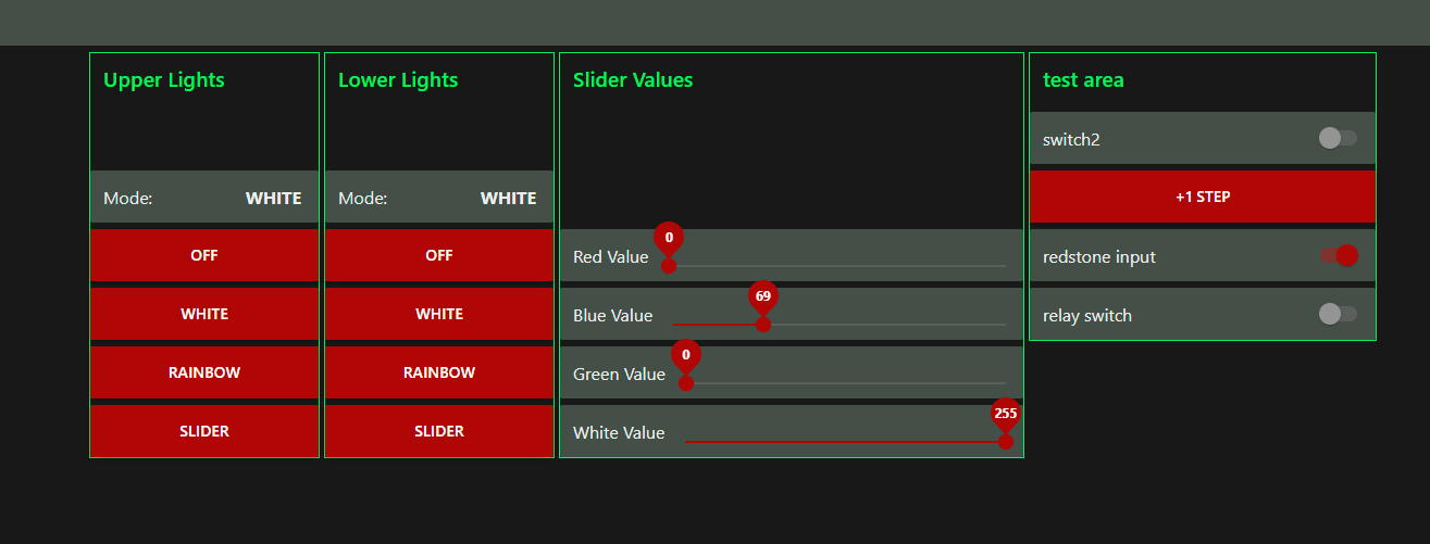
Design basic UI page to reflect current states
ESP32
Set up a small breadboard with LED assigned to subscribed topic
Research connection hardening for ESP32
Breakdown of ESP32 Security Features
https://docs.espressif.com/projects/esp-idf/en/latest/esp32/api-guides/wifi-security.html
https://blog.espressif.com/understanding-esp32s-security-features-14483e465724
https://blog.espressif.com/esp32-tls-transport-layer-security-and-iot-devices-3ac93511f6d8
Experiment with OTA updates
https://randomnerdtutorials.com/esp32-ota-over-the-air-arduino/
VSCode
Take some notes on how to manage github repo and PIO projects
PlatformIO
Create a Repo that contains multiple PIO projects
Create PIO projects for the following functions in isolation
ESP32 Blink
ESP32 WiFi.h Connection
ESP32 PubSubClient.h Connection
ESP32 WiFi+PubSubClient Connection
ESP32 Breadnet LED
ESP32 Mega Lights 2 Test
ESP32 Mega Lights 2 Final (own repo)
2022-j
Breadnet
Deploy Something Useful on Breadnet
ESP32 OTA Updates
Finish Foundational ESP32 Script
Harden Breadnet Security
Set up a Breadnet Domain
Set up a basic MongoDB on the Pi for Node-RED to interface with
BN – Breadnet
Setting up on new router
Had to change all the 10.0.0.x back to 192.168.0.x
router pass g
After struggling to port forward anything, even a simple minecraft server, I looked up a list of common port forwarding issues, and one listed was that a lot of people don’t even realize they’re actually behind multiple routers. And so I installed a router counter and it turns out I am in fact behind two routers, the second one is mine, and the first is the AT&T thing in the garage
http://www.pcwintech.com/shanes-toolbox
My Router
192.168.0.1
ATT Router
192.168.1.254
Okay so
DLINK Router (mine)
Simple Port Forward
Just add a custom service to your IP
Device IP
ATT
Use Device Access Code found on back of router
Firewall
NAT/GAMING
Manage Custom Services
Create a Custom Service with the port you’re trying to open
Add the Custom Service you just made, and select the Device it’ll apply to
In this case, the device is the second router
192.168.1.65/unknownecade02eff78
Rinse and repeat for each port you’re opening
VSCode uploading to wrong port
You can specify which port you upload to
[env:uno]
platform = atmelavr
framework = arduino
; any port that starts with /dev/ttyUSB
upload_port = /dev/ttyUSB*
; COM1 or COM3
upload_port = COM[13]
Bare Minimum Breadnet Achieved
Raspberry Pi running Node-RED and MQTT
Port Forwarded
1880 for Node-RED
1616 for MQTT
ESP32 MQTT Connection Test
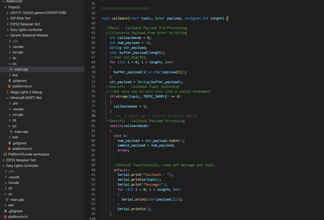
Setting up a fundamental script, making sure it’s clean, documented, capable, and commented so I can return to it in the future.
Not sure how to structure these notes for now but
in void reconnect(), make sure all topic subscriptions are in this
The first time the MQTT network is connected to is in the reconnect function which is called in loop, so technically there’s no setup for it
in void setupMQTT()
the setCallback function only gets called once and assigned once per mqtt instance, so I think everything has to be inside the singular callback function
So really, theres only three important functions in the program
void setup
void loop
void callback
Speed Test
I ran an unconditional publish script to post “AAA” every loop and it posts very quickly. It can do about 10 posts/millisecond
so 10,000 posts a second? jesus
Topic Char* issues
referencing the char* that is the “topic” variable in the callback can’t be referenced to use the topic itself as a string for a future messages payload
meaning, I’m trying to make the payload for a response message to be the topic of the initial message, and it’s not working
Node-RED Booleans
Node-RED boolean switch outputs yield a string of ‘true’ or ‘false’
so instead, make the payload numbers of 0 or 1
MQTT Outputs
Binary-Ascii Characters Table
https://www.binaryhexconverter.com/binary-ascii-characters-table
The payload comes in the form of a byte
If you cast that byte as a string and print it to the serial, you’ll get the ascii code for that binary
example
payload: 0
instead of getting a string for ‘0’
you get a string in binary that represents the character zero
I can’t figure out how to get a number
MQTT passes ASCII data
so even number 0 results in 48
I can print back on ESP32 in Serial the payload byte and get 48
I can print back the char(payload) byte and get 0
but that’s still a char, I can’t get a numeral zero to work with
Success!
byte -> char(byte)
String(char(byte[n]))
int num = String.toInt()
Code
case 3:
Serial.println(payload[0]);
Serial.println(char(payload[0]));
//String popcorn;
popcorn = String(char(payload[0]));
Serial.println(“popcorn”);
Serial.println(popcorn);
shrimp = popcorn.toInt();
Serial.println(“shrimp”);
Serial.println(shrimp*5);
if(shrimp*5 > 12)
{
Serial.println(“you did it!”);
}
Waiting to upload to github until I clean it up more and demo it a bit, but wanted to write it down
It seems like I also need to convert the post-calc integer back into a char format in order to publish the results
Finally
server delivers a BYTE*
ESP32 takes BYTE* and converts it into a CHAR
then stores that CHAR into a String object
then String.toInt() to get an INT
then do math on that INT
then itoa() that INT into a CHAR
then publish that CHAR back to the server
Flag Colors
Red
176
5
5
Black
24
24
24
Grey
69
79
71
Green
0
242
98