
3/14/2022 – 3/27/2022
Mega Lights 2 Demo: https://youtu.be/sEQk2R4pPQM
Summary: My objective was to finish routing the Synth PCB and place the order on JLCPCB, then start Planning and Purchasing for Mega Lights 2. I wasn’t sure if I would get delayed from the lights or from the synth, but that didn’t end up happening so as soon as I placed the order for the Synth PCB, I was able to get started on the lights.
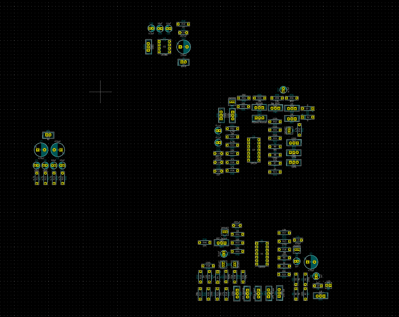
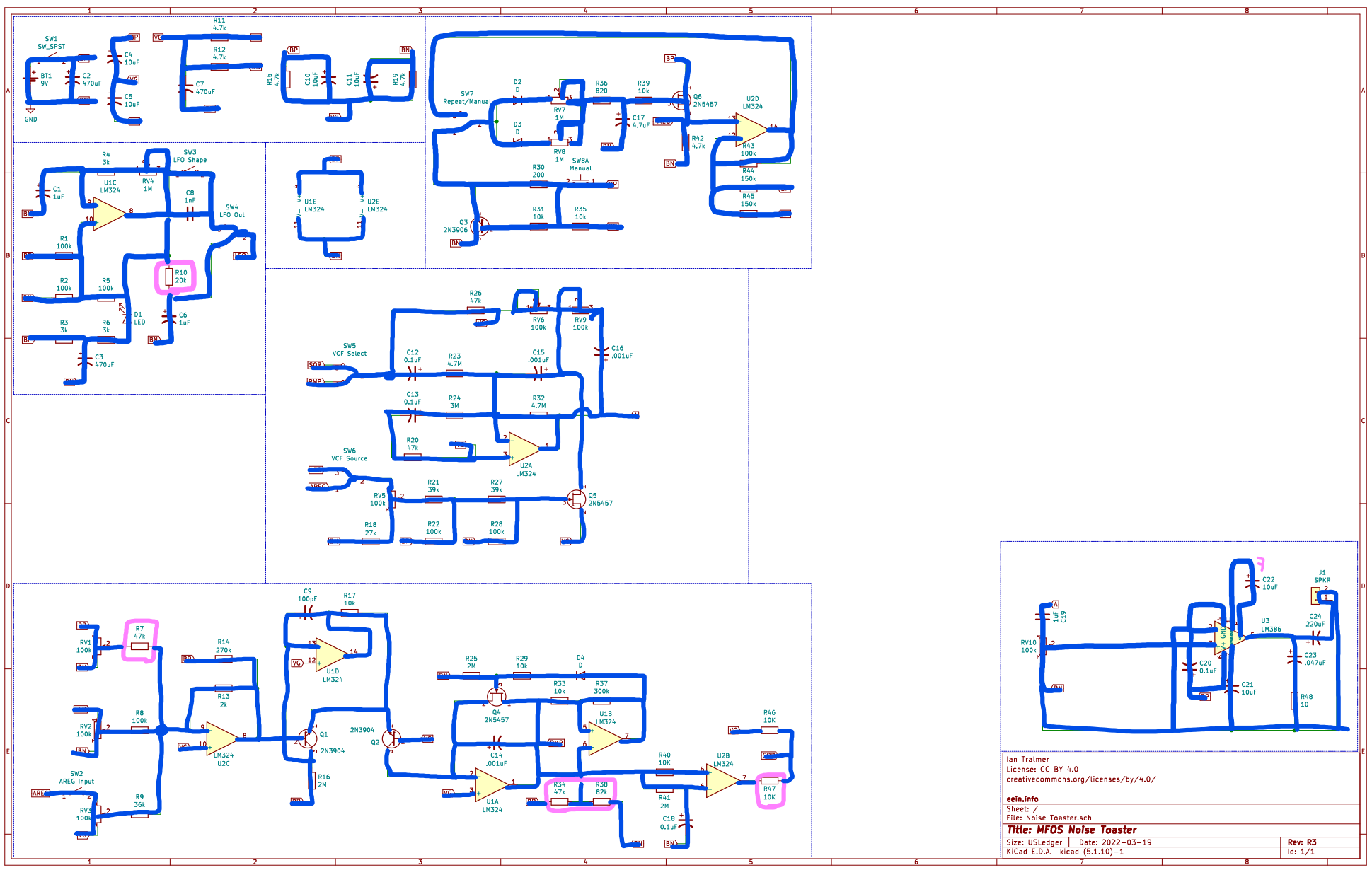
For the Synth PCB, I rerouted the thing about 5 times, got some advice on routing from Tyler, and made a perfectionist effort to try to fit it into as tight a footprint as possible. I managed to get it into a 150mm x 75mm frame and it looks pretty good to me. It’s my first time attempting to route anything with meaningful signals, so I’m not sure how it’s going to come out. I’m a little worried I’ll solder the whole thing together and it simply will not work. Either I put something down wrong, or there’s a design flaw with the board. Both are annoying but one costs time and money. I don’t see any other way around that risk though. I sanity checked and verified the PCB routing matches the netlist from the schematic, and verified the KiCAD schematic against the original author’s schematic, and triple checked those against the breadboard. There’s not really much more I can do past that, so we’ll see what happens.
What comes next for the Synth is creating the JST-XH connectors that will wire the potentiometers and switches to the front panel. Along that line, I also have to order the pots and switches. I’m not going to start designing the case or the front panel until I have a working PCB with all the pots and switches just laying around. On the bright side, if there’s a critical flaw with the PCB, I can keep the pots and switches and just hot swap them over to the next PCB later. Since they’ll be the main UI to the board and are part of the circuit, I need to make sure the connections are sturdy.
For Mega Lights 2, I got the 10m of the SK6812 RGBW individually addressable strips on a black PCB strip in the waterproof silicone sleeving from my mom for my birthday. That saved me about $200 (thanks mom). And my brother got me the aluminum railings. To add some polish to it, I also got some 3-pin ribbon cable, some JST connectors, and some RGB strip adapters and right angle turners, as well as some more cable mesh sleeving. I also purchased a 5V 12A power supply unit and a set of dremel bits, mainly because I wanted a diamond cutting wheel to try on the aluminum, which worked much better than using a hacksaw, like I did last time.
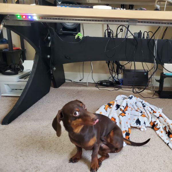
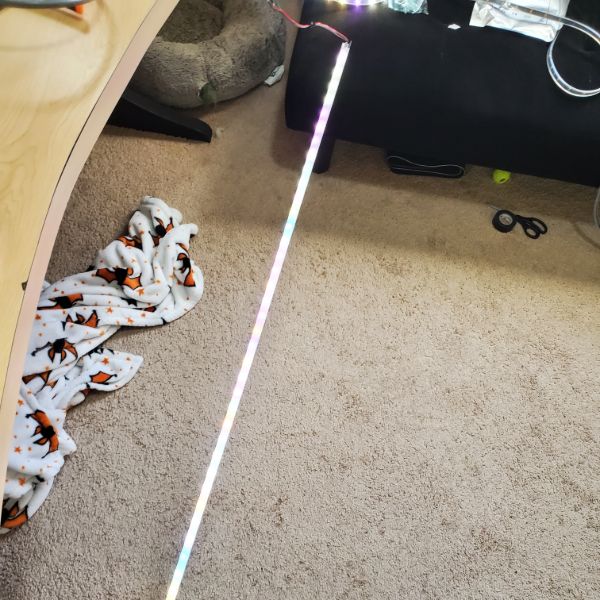
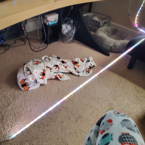
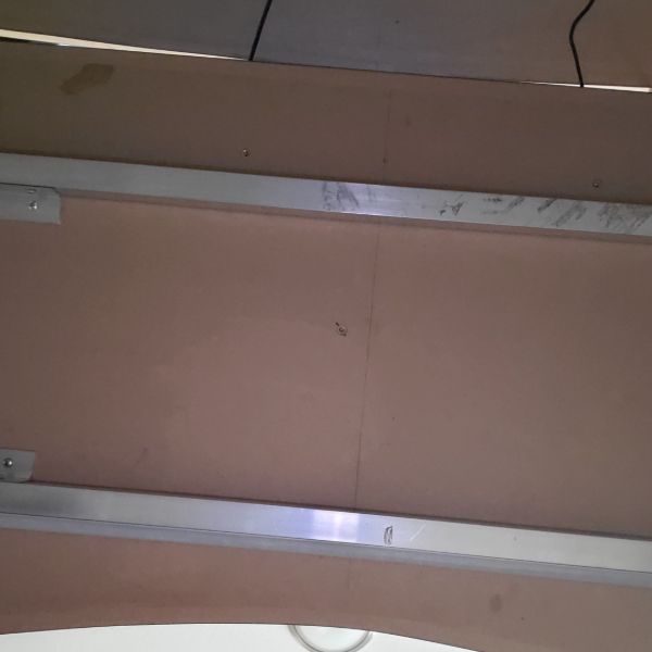
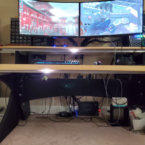
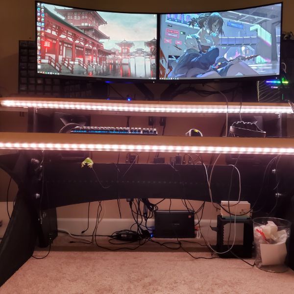
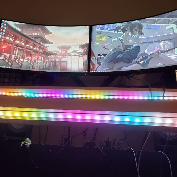
I was able to install two of the four railings I planned out but the remaining two are a little trickier to get installed and will need some extra hands and extra planning. I haven’t looked into the software that closely yet, but I’ve got some sample code that works well enough for now. I did figure out that I’ll need the microcontroller running two separate PWM signals from two unique pins if I want to be able to control the top and bottom desks’ lights independently.
Once all four strips are mounted and the cables have been managed to my satisfaction, I’m going to design an enclosure to house the PSU and the microcontroller that will manage the lights and send the PWM signals. Eventually, I’m going to set up Breadnet 4 and have the lightsbox connected to the home network so I can update their patterning over the air, but for now, I’m satisfied just using an offline arduino in there and manually updating the pattern when I want. It’s not that big of a deal to me at the moment, but I do want to finish installing everything.
For the next two weeks, I plan on finishing the lights install and getting a simple enclosure working for now, then pivoting over to soldering together the synth. Whether the synth works or not, it’s going to eat up a bunch of my time. Hopefully it works first try, that’d be nice. Once I’ve reached a wall with the synth, either because it doesn’t work and I need to order a new PCB, or because it just works, then I’ll get back to designing the enclosure for the lightsbox. After the lightsbox enclosure is done and I have a working PCB for the synth, that’s when I’ll design the front panel and housing for the synth. Once these two projects are wrapped, I’m moving on to the power supply unit, and then after that, I’ll probably pivot into reading AoE for a few months. Not sure yet.


Frog
Resources List
Monty Choy Hardware Interview Questions
1
Digital Design HQ Discord #Resource Dump
2
EEVBlog Power Supply Design Series
3
Intel FPGA Technical Trainings
3
Digikey intro to RTOS
4
Digikey intro to FPGA
4
Digikey intro to KiCad
4
FesZ intro to LTSpice
4
Tutorial Sites
Asicworld
ZipCPU
Nandland
cplusplus
Practice Problems for Hardware Engineers.pdf
FPGA4Fun
Nandgame
HDLBits
EDAPlayground
FPGA4Student
Bitsolver
5
Art of Electronics
5
Automate Boring Stuff with Python
6
C++ for Embedded Systems
6
3D Printing Dive
7
FreeCAD Tutorials
7
Timeline
Original Plan
New Plan
January
A
3D Printer
B
3D Printer
A
3D Printer
B
3D Printer
February
C
Power Supply
D
Power Supply
C
KiCAD/LTSpice
D
KiCAD/LTSpice of Synth
March
E
Power Supply
F
Interview Questions
E
Breadboard of Synth
F
PCB Routing for Synth
April
G
Interview Questions
H
Intel/Quartus
G
LED Strip Installation
H
LED Strip Backend
May
I
Tutorial Sites
J
Tutorial Sites
I
Power Supply
J
Power Supply
June
K
FPGA Projects
L
FPGA Projects
K
Interview Questions
L
Interview Questions
Interview Questions
4 weeks
Intel FPGA
2 weeks
FPGA Projects
4 weeks
Power Supply
6 weeks
3D Printer
4 weeks
C/C++/Python
Verilog
Art of Electronics
4 hr/day
4 hr/day
2.5 pages/hr
5 pages/hr
24 min/page
12 min/page
10 pages/day
20 pages/day
100 pages/sprint
200 pages/sprint
200 pages/month
400 pages/month
6 Months?
3 Months?
(3/16) Mom said my present should be arriving today. Bub asked me how much railing I need so I’m guessing she bought me my LEDs. Which is pretty exciting.
I’m thinking my lab sequence will be
Synth PCB Layout, Order
1 week (this week)
Research how to install strips
1 week
Install Strips, set up backend
1 week
Assemble Synth PCB, Validate
1 week
Start Power Supply Design Series
I can tell I’m kind of avoiding the Power Supply Project
Synth
Order PCB
Solder
Model Housing
Design Front Panel
Polish
Mega Lights
Dive in NeoPixelBus Library
Some OOP?
VSCode/PlatformIO/Github Setup
Hardware Mounting on Desk
Setting up Breadnet IV
NodeRED, MQTT, Tkinter, etc.
Power Supply
Interview Questions
Art of Electronics
Map Interview Questions to Page numbers in AoE
Automate Boring Stuff with Python
Design Christmas Present
Sprint Objective
Finish Routing Synth PCB and order
R1, R2 Notes
Routed the board about three times now
I’ve tried different methods and I’ve come up with a few design principles that work for me for now, as a beginner
I’m having a lot of success using one layer for vertical traces and one layer for horizontal traces
This becomes a little more complicated in traces that are mostly equal in rise/run & are diagonal.
I feel like Vias are a copout cheater move, so I don’t want to use vias whenever possible, but Tyler told me he’s been enlightened and Vias are fine, good, legal, and necessary
With that as the case, I might be more open to making diagonal runs go in two layers, with vertical, and then horizontal segments
In addition to that, I also route power and signal lines first, then fill in the rest.
I realized about 2.5 routings in that I could use copper pour, but I’m not sure how effective that would be for my purposes
Tyler advised me that any coupling capacitors for the opamps will be basically ineffective if they are too far away, and that I should place them closer. I’m not sure if I’m even ready to worry about something like that right now though.
I’m not sure this whole thing will blow over later on once I print it out.
I’m thinking it might be worthwhile to pass the schematic and final board layout off to hempler and/or tyler so they can review it for me before I print.
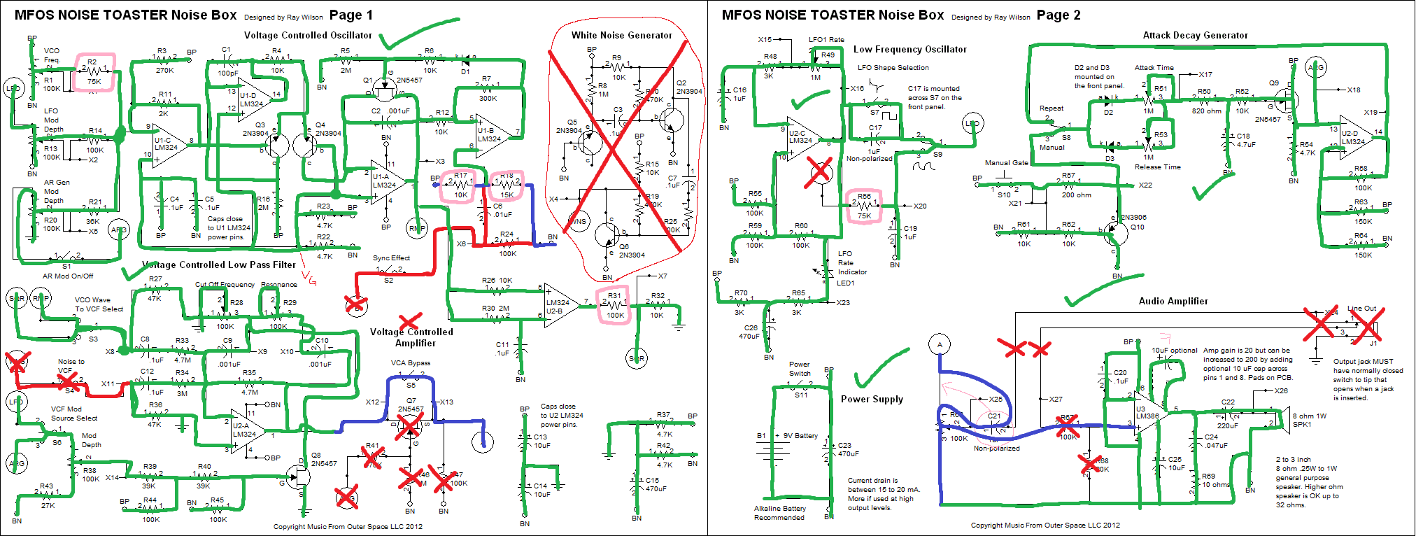
If I were to do that, I would take a copy of the original schematic for the Noise Toaster, redline it, and then pair that with the schematic that formed the netlist for the PCB routing.
I would send the schematics to hempler to cross check, and then the pcb layout and the schematic to tyler for layout critique
Along with that, I should mentally prepare myself for the frustration of having to pay for printing this thing like 3x, and to have to solder the whole thing together only for it to not work at all, probably about 3x as well.
As much as I want to minimize the risk of that happening, this is my first complex board and even just routing it I can tell that I’m a total amateur, and there’s a serious at form behind this.
It does make me wonder what kind of crazy AI we have right now that can design something like this optimally and automatically
Along with keeping copper pour in mind for the ground pins, Tyler also warned me that if my ground traces are long, I need to make sure they are fat, or I will end up with Ground Loops. There’s clearly a lot in this area I don’t know about
I can see myself rearranging and rerouting this thing many more times. I can tell each iteration is getting better than before.
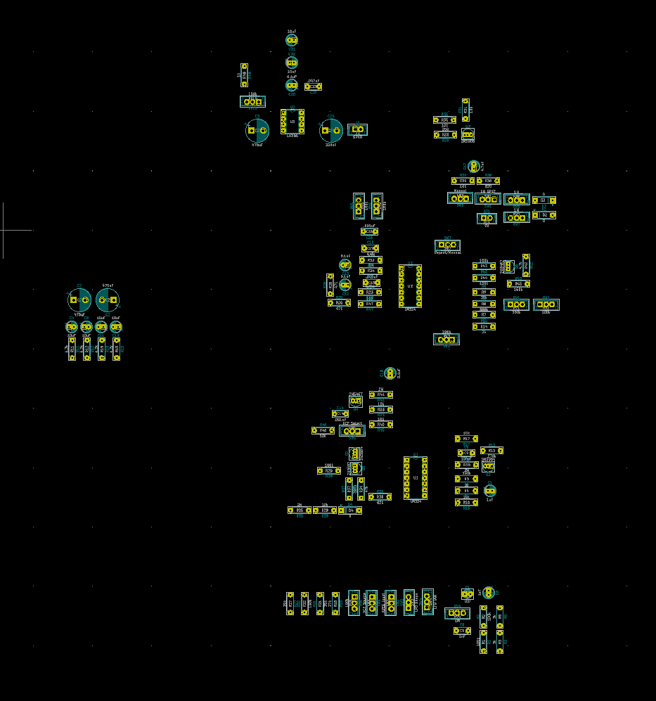
It took me a while to accept that it simply takes time to position and rotate each component in a meaningful way to allow the layout to be any degree of effective
The board size is looking around 100mm x 160mm at the moment
R3 Notes
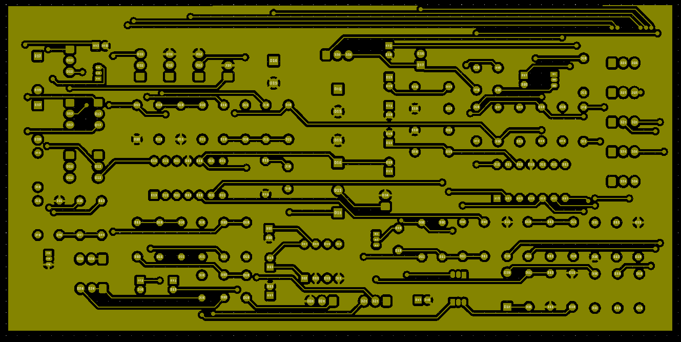
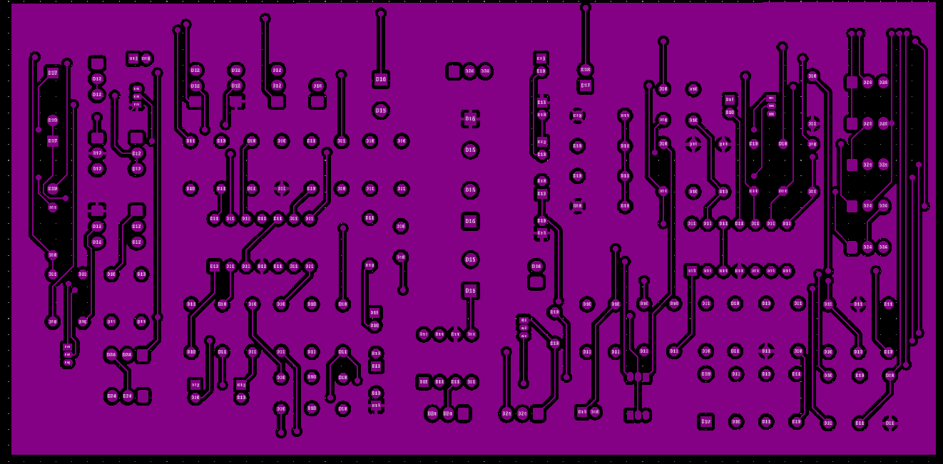
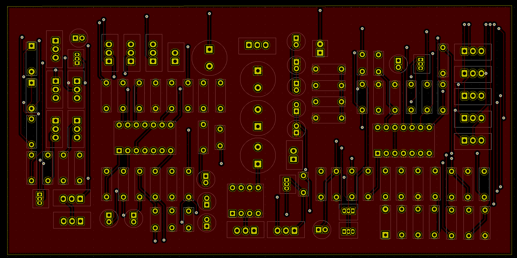
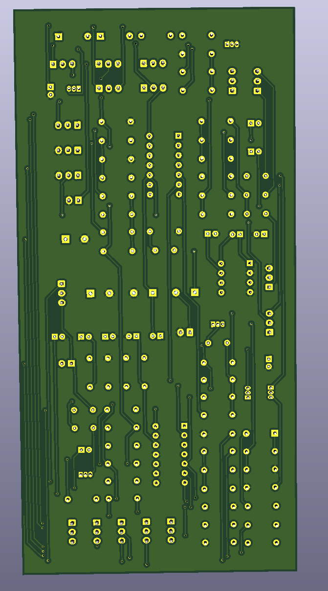
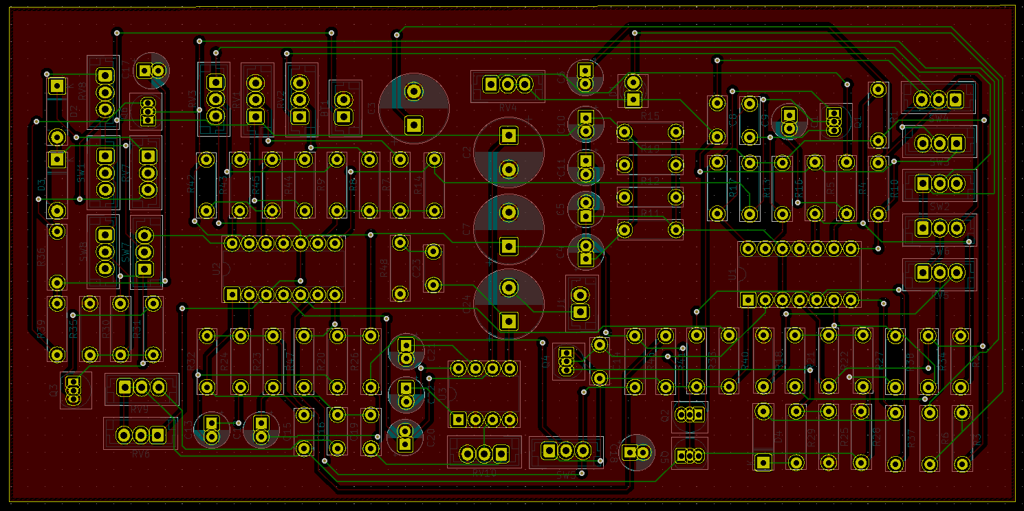
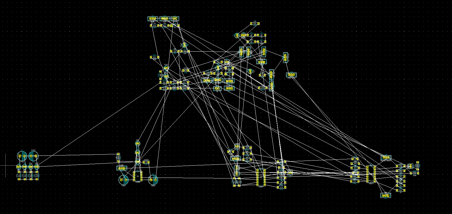
I tried routing using as many vias as I wanted in order to keep all the backside lines vertical and all the frontside lines horizontal. It worked out pretty well. 41 vias total.
I also didn’t route Ground / Net BN and used copper pour at the end to fill it in
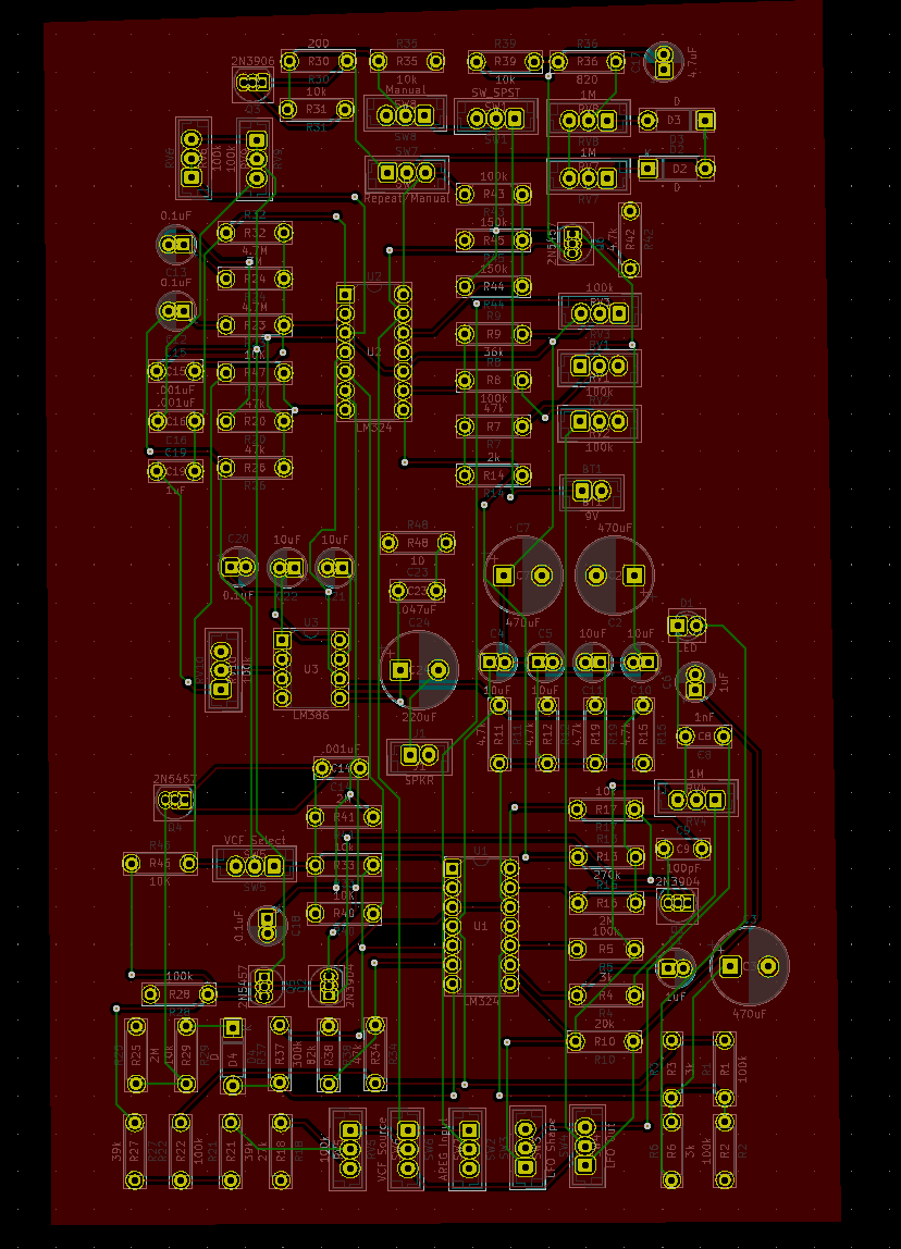
As I expected, since the board is taller than it is wide, the copper pour should go on the front side, where the horizontal traces are less complex and less prohibitive
Putting the copper pour on the backside with the green results in some unfinished connections in the ratsnest
That’s the best one yet for sure, so I’m going to redo it once or twice more after positioning the silkscreen names on the board, to polish it up more
I’ll also probably reposition some stuff as well
R4, R5 Notes
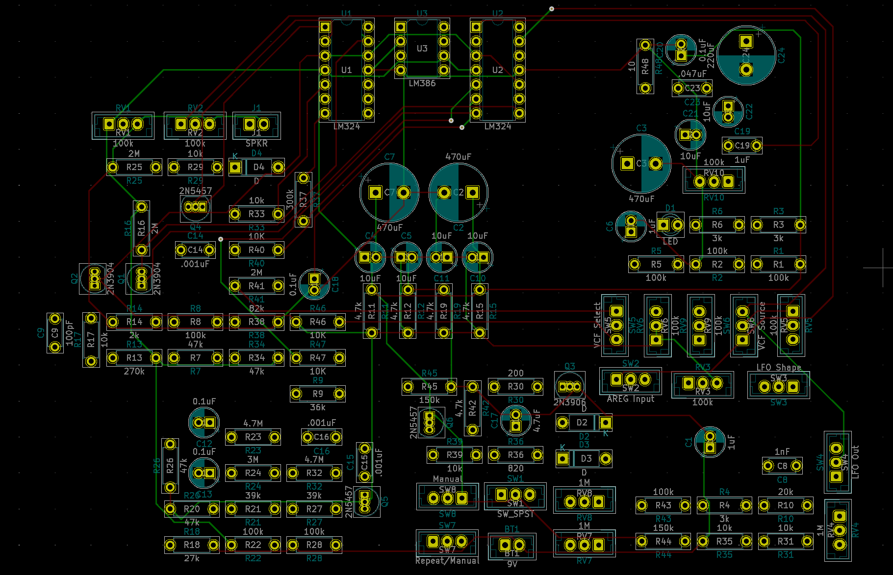
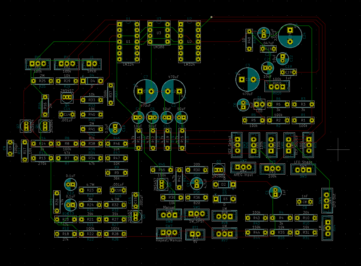
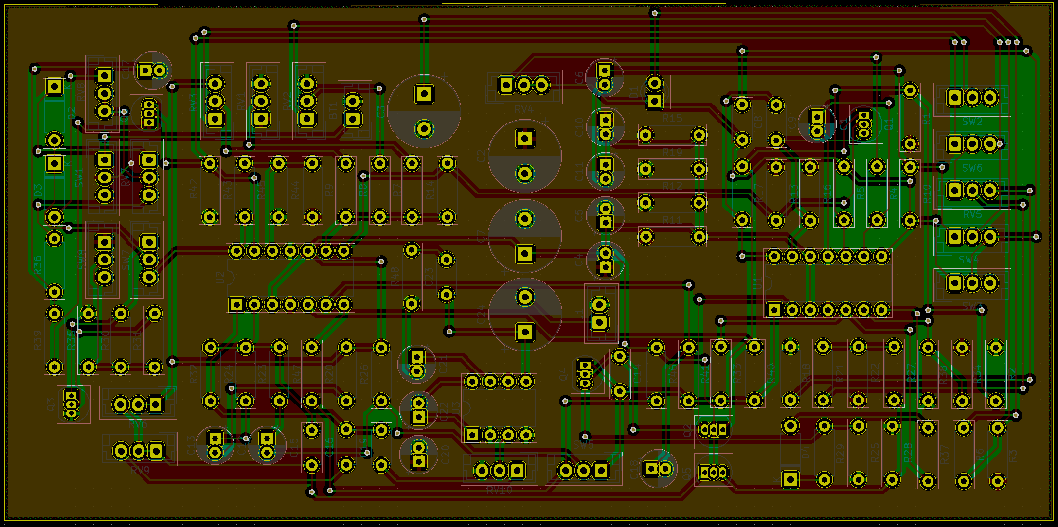
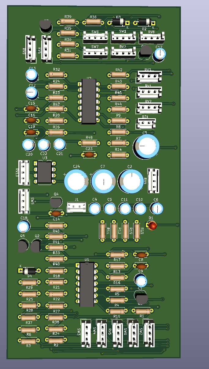
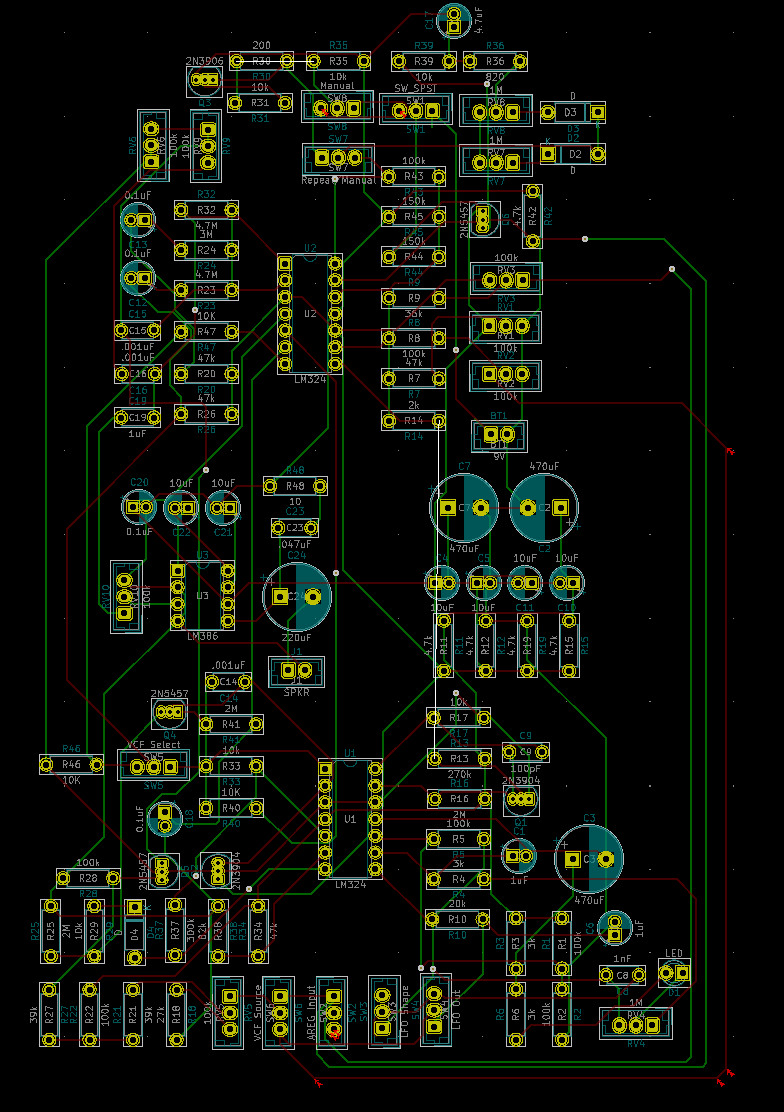
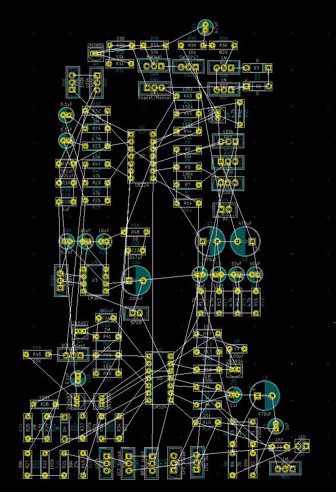
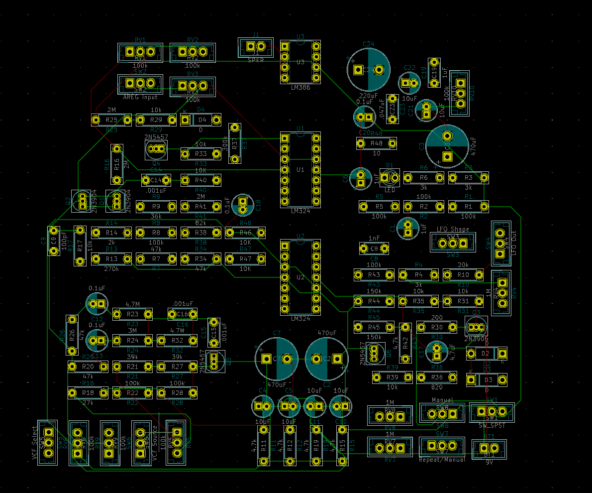
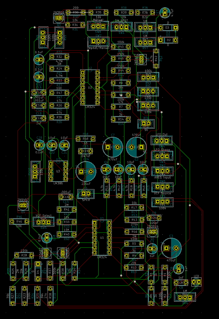
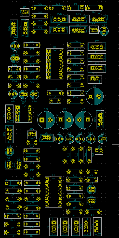
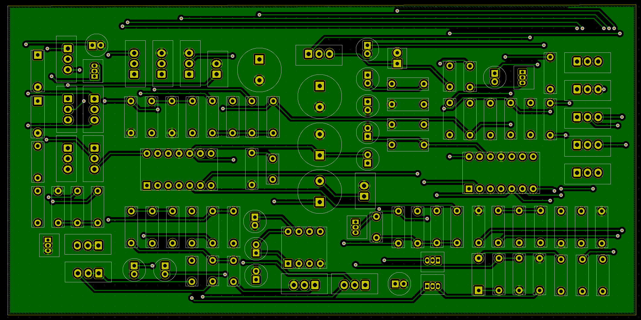
After repositioning all the silkscreen reference designators, I also took the time to reorganize some of the components and fit them all into a much denser, more perfectly rectangular footprint. That’s probably the most important thing I did today besides adding a second copper fill
Now there are two copper fills, one on toplayer for BP and one on bottom layer for BN. There were a couple connection points where the copper fill zone didn’t connect every single BN or BP, so I had to go ahead and bridge some of connections before redoing the fill. That didn’t disrupt the flow of the board at all though.
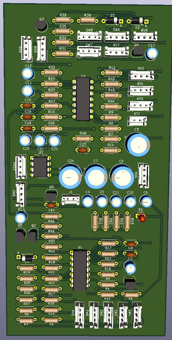
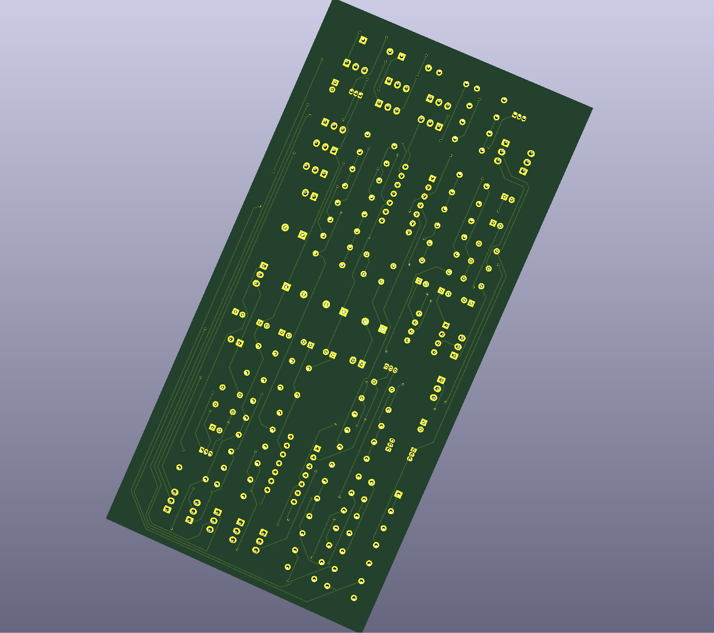
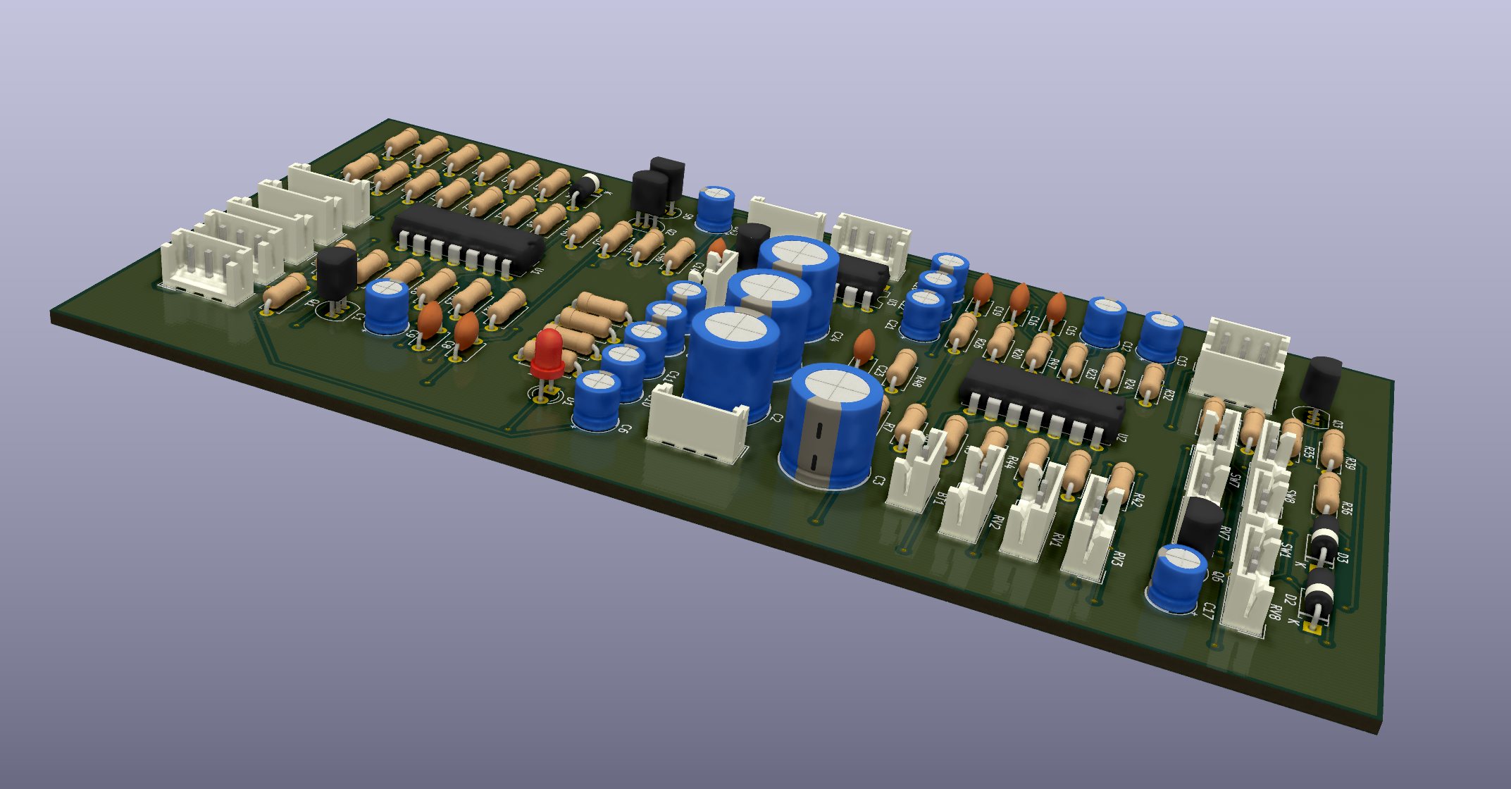
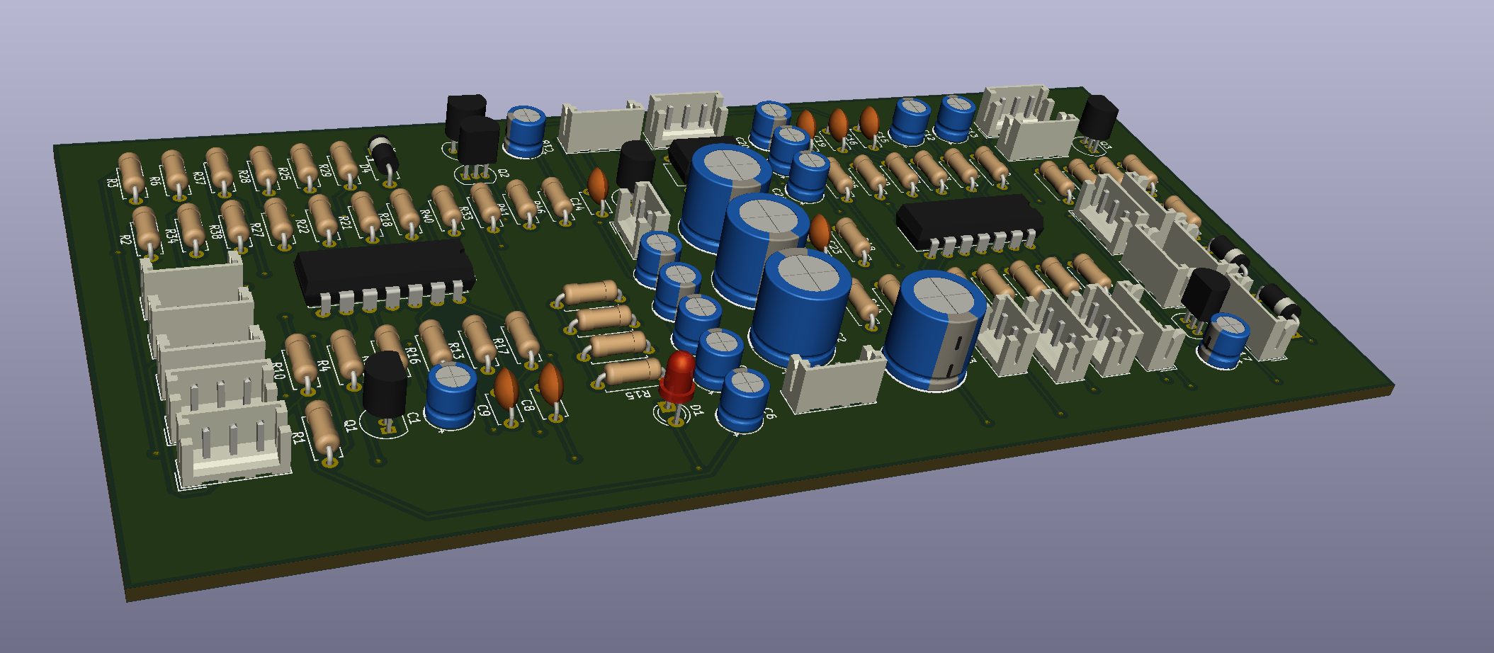
Once I took a look at the 3D Viewer’s render of the board, a lot of stuff started to click, so I rerouted once more to make it lok even better.
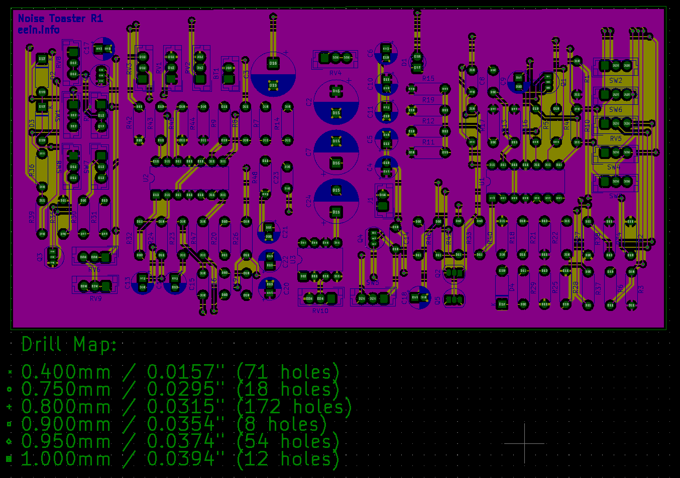
I’ve started getting more comfortable using vias very liberally. R5 has 71 vias.
I also have gotten a good enough eye to see how some traces are going to interfere with other traces, but that’s primarily because I’ve gotten very familiar with the problem areas on the board.
Along that line, I took the time to identify all the long distance connections that wrap around the corner of the board and aligned them all so they don’t look as ugly.
On R5 there was one line in that group that I caught too late and would’ve had to redo basically all of the long ones in order to fit it in properly
I also noticed the JST connectors were often flipped or rotated and not facing the same direction. I rearranged things even if that made it more complicated to route, so it would look more polished in the 3D viewer.
As of R5 the 3D view looks solid. Dense and Polished.
The board’s dimensions are around 140x65mm with the extra room for the traces.
I checked on JLCPCB and it costs more to get any board that isn’t 100mmx100mm
I’m at a decent stopping point for it now so I think I’ll pass this onto tyler and ask him to take a look at it so I can move on from this and finally place the order
I feel like I’m quickly developing a skill and appreciation for the creative thinking that an elegant board layout requires. I’m sure it gets even more extreme with high speed signals, more than two layers, and SMT components
PCB Sanity Check Before Ordering
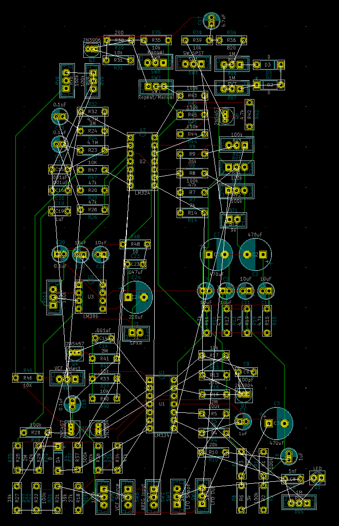
Opened Schematic, Exported Netlist, Imported Netlist to PCB, No changes to the ratsnest.
Now to check the KiCAD schematic against the original schematic and mark changes
Discrepancies
The fake VG on the schematic that connects to the positive end of the op-amps throughout the VCO is actually tied to VG on my schematic
The resistor in the RC on the non-square output of the LFO is listed as 75k on the official MFOS, but it’s 20k on my breadboard and on my schematic and seems to work just fine. Not Changing
Flag “B” removed, LFO sync feature removed
Bypass Cap on LM386 1-8 can be put in either direction. Positive side faces pin 1 on schematics, but is reversed and functional on breadboard
First output resistor on SQR wave is 100k on MFOS schematic, but 10k on KiCAD. Breadboard has 10k, works fine as is. Am interested, but Not Changing.
Second Opamp on VCO has threshold voltage adjusted, no sync effect, just replaced with a voltage divider.
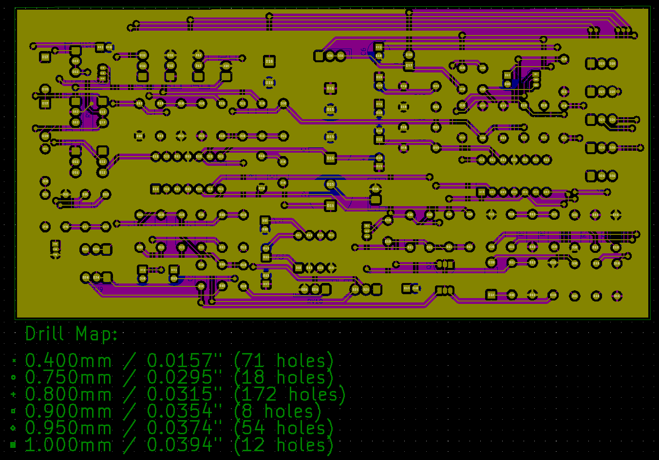
PCB Ordering
JLCPCB Ordering Instructions
https://support.jlcpcb.com/article/149-how-to-generate-gerber-and-drill-files-in-kicad
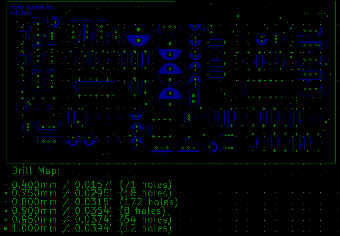
Gerbers Generated, Drill Map Generated, all layers double checked
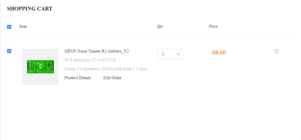
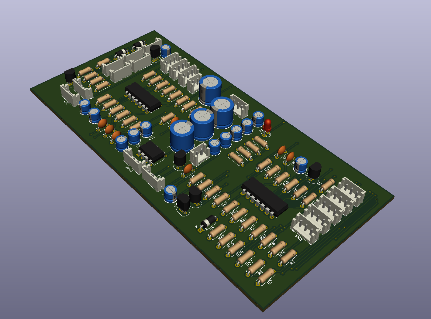
Placed order on JLCPCB for a total of $23.73 for 5 boards at 150x75mm
Only thing I didn’t add was mounting holes, which should be fine. I can drill them myself later if I need to.
MFOS Noise Toaster R1 PCB ordered – 3/19/2022
Start Monty’s Interview Questions
Soldering Skills Deep Dive
Plan and Purchase for Mega Lights 2
PCB Routing Guides
Common Mistakes
https://youtu.be/4FMW0_ZI48I
1. Being Impatient in Component Placements
2. Not Considering Routing Directions
Pick Vertical or Horizontal for each layer
3. Not using wider traces for higher current
4. Not making use of copper pour
5. Improper attention to spacing
PCB Layout Review and Analysis
https://youtu.be/xhRhsCVF8mE
Try to keep all your signal traces on one layer
Try to keep all your power traces on one layer
Don’t let one power trace cut off multiple signal traces
Try to keep loop area low, as it affects EMC and other stuff
A Bypass Cap with a huge loop area is ineffective
Try to avoid jumping layers with traces unless it’s with a non-critical trace, at the end of the design, and you’re at wits end.
Always handle your critical traces first. Obviously
I2C lines are not critical and can be as long as you like
Matched-Length traces are important, but it’s less important with short traces
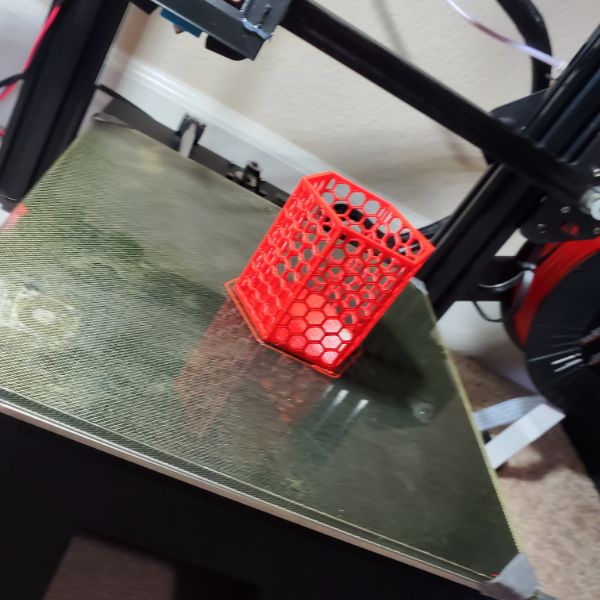
3D Printer
Manticore
Got some spaghetti, changed Z Probe offset from -2.70 to -3.15, looks like it’s working now
Continued tweaking. Took out filament and cleaned the nozzle, I think there was a jam because it’s printing better now.
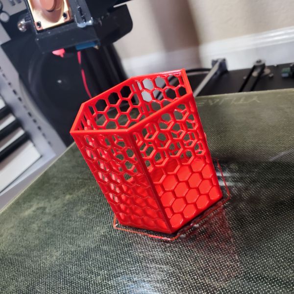
-2.60 is too far I’m pretty sure
-2.70 is what I had before but the nozzle sometimes collides and creates distortion, so I raised it to -2.675 and saw better results right away
-2.80 is far too close and prevents proper extrusion
Used steel wool scrub on the PEI bed as well to refresh it, just in case
First layers are good again. Still experiencing some stringing on retraction and when it makes large jumps the filament doesn’t immediately stick which is a problem that creates small pockets of spaghetti
Mega Lights 2
Some soft testing before moving into hardware. This could dramatically affect how the system gets wired
Test Neopixel Libraries using an Arduino and a PSU
Set up VS Code or Arduino IDE for testing, debugging
Need to confirm strips can be controlled in parallel
Need to confirm addressing system for strips
Setup Testing
SK6812RGBW Product Page
https://www.adafruit.com/product/2824?length=5
Hardware Strip Prep and Test
I have two strips that are both 5m long that have 30m/LED or 150 LEDs total
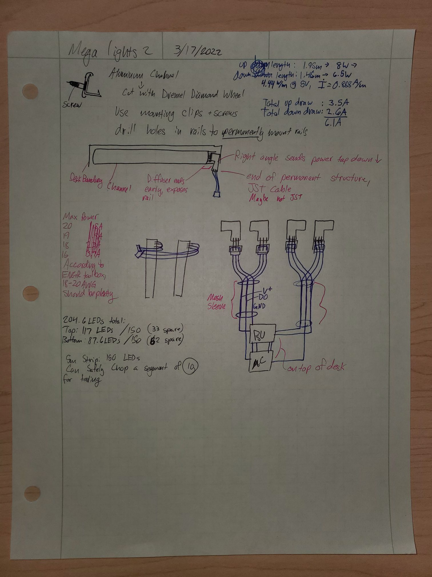
Top length is 1.95m x 2 = 3.90m x 30LED/m = 117 LEDs out of 150 leaving 33 to spare on the first spool
Bottom length is 1.46m x 2 = 2.92m x 30LED/m = 87.6 LEDs out of 150 leaving 62 to spare on the second spool
This means I can take off a 10 LED chain off of either spool without much consequence
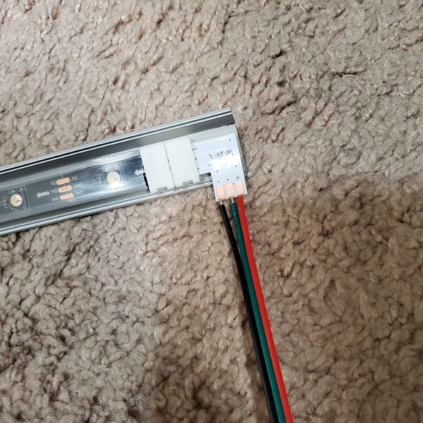
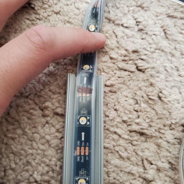
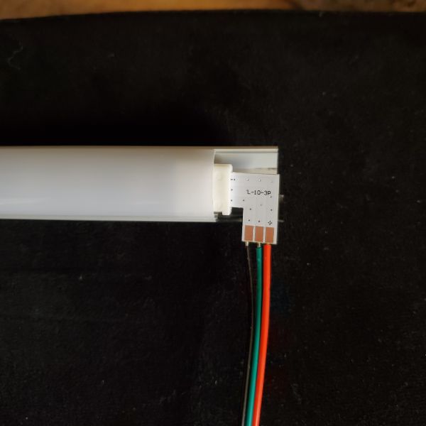
The strip comes in a watertight silicon sleeve and has terminals at both ends
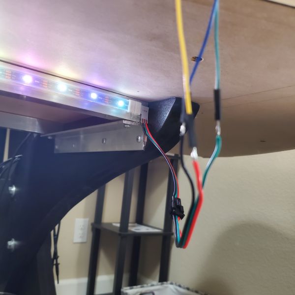
The terminal has a power wire, a ground wire, and then a 2-pin JST with the same ground, and a data wire. This is so I can connect one set to the power supply and the other to the microcontroller and have them both already sharing a ground.
Once I cut into the silicone sleeve, that’s something I can’t really undo. I’m not sure if I can take the strip out of the sleeve, or if that’s something I even want to do, but there’s a chance that could get ugly. Either way though, I need to get some LEDs off of this spool for testing. Even if I didn’t, I would eventually have to cut it for the desk mounting, so let’s figure that out
Both ends have the same terminals, so it doesn’t matter which end I cut
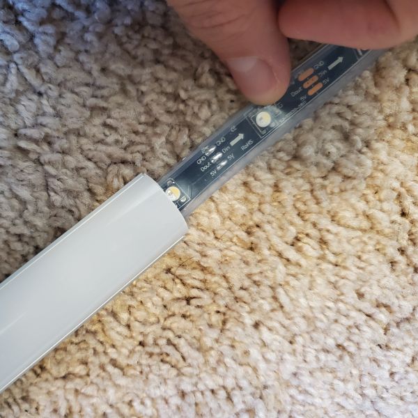
Actually, it does, because there’s a directionality to it. There is an arrow pointing across the strip that appears between each LED. So I’ll cut on the side of the arrows origin (X) —> ()
Sharpie sticks to the silicone pretty well. Comes off with some mild finger rubbing
Scissors can cut right through the silicone and the strip with ease. Not a problem, just take it slow and do it precisely
Stripped all four wires and crimped on some GPIO connectors to the strip of 10 LEDs. Time to connect to the arduino and test the Neopixel Library
The silicone sleeve can be easily cut by scissors, so extraction is pretty straightforward. The sleeve can be separated simply by pulling apart the seam on the side after a pilot cut. Since there are terminals embedded in silicone and a bunch of glue on one end, it’s not that simple to slide it out. But at the same time, there’s no way to get those terminals out of the silicone, so if you want the entire thing removed from the case you’re going to have to cut and resolder the terminal connectors anyway
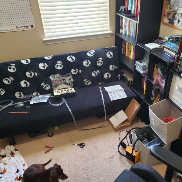
More Rigging
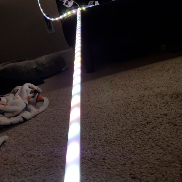
I was eventually able to figure out while looking at the cyclone animation, why the pixel counts seem to be off. I have to increase them to a number higher than there are actually pixels on the strip I selected. It’s because the programming expects a RGB strip and the strips are RGBW and so they expect an RGBW signal. I haven’t looked that closely into it, but I noticed the Red/Blue/White pattern on Cyclone actually wrote a Green color to the pixel and then updated that same pixel to White before moving on. Which means that it’s writing that pixel twice and counting it twice in the total length of the strip.
This means that I can get the strips to function properly if I just multiply the actual pixel count by 4/3. That’s something I can fix later in software, but for now it means the strips are working properly.
I’m also noticing now that I have two strips of different lengths running concurrently, that two strips attached to the same data pin will simply perform the same commands in parallel, and mirror eachother. There doesn’t seem to be a way to convince one strip that it exists at the end of the other, or anything like that.
That means that in order for there to be two color commands, or two concurrent animations, there need to be two PWM signals coming from two separate pins on the uC. I still haven’t dove into the software so don’t know if that’s even something I can do with the libraries, but I don’t really see any reason why you shouldn’t be able to manage two PWM waves with on Arduino.
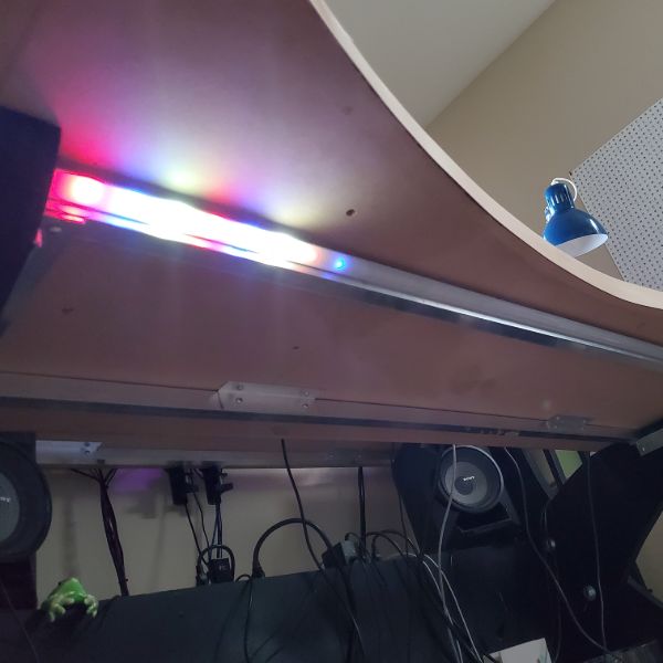
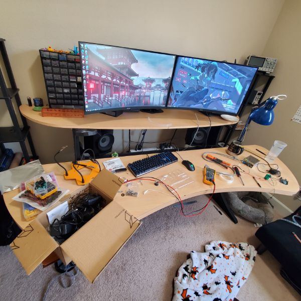
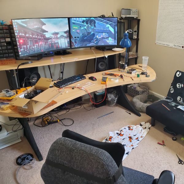
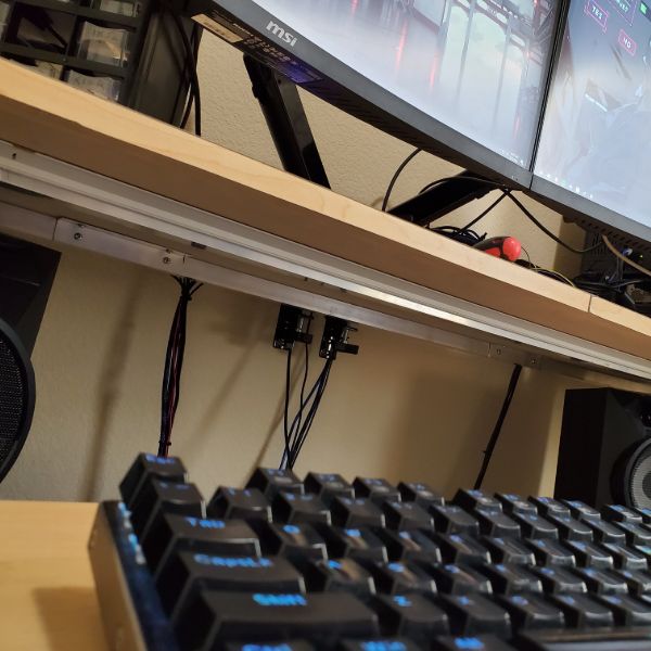
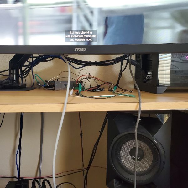
For mounting the back rail on the upper desk, the worst case scenario is that I have to undo all my cable management, take off the computer, and the component drawers, AND un-mount the monitor rack, take off the monitors, take off the upper desk, and THEN install the rails.
I don’t really want to wait until the next time I move to disassemble the desk and install the last piece of this thing, so I’m guessing the best available alternative is to use a large amount of the double-sided tape and carefully press it up to the desk. The tape performs pretty poorly when its exposed to air at all, but if both sides are flat and flush against a material it seems to last much longer. The only issue with this plan is that I don’t think I’ll be able to get it into position and adhered alone. The margin of space I have to work with back there is so low, I don’t think I can get it in without a second person, and without moving my 5-shelves in the corners.
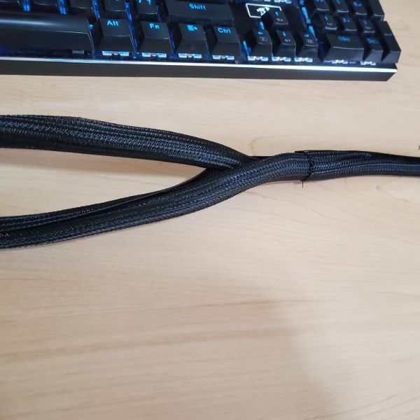
What I can do though is work on the wiring harness. I’ve got a spool of 3-pin ribbon cable and some mesh cable sleeves. I need to figure out how to run two sleeves into eachother in an elegant way for it to look decent, but I don’t think that’ll be an issue.
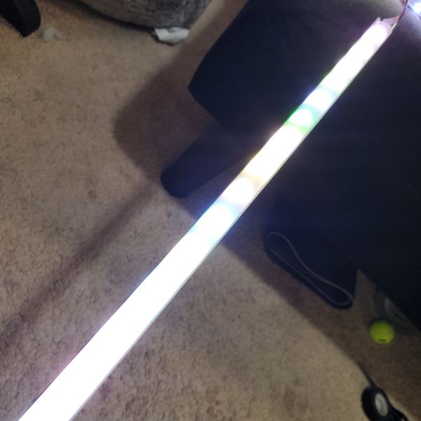
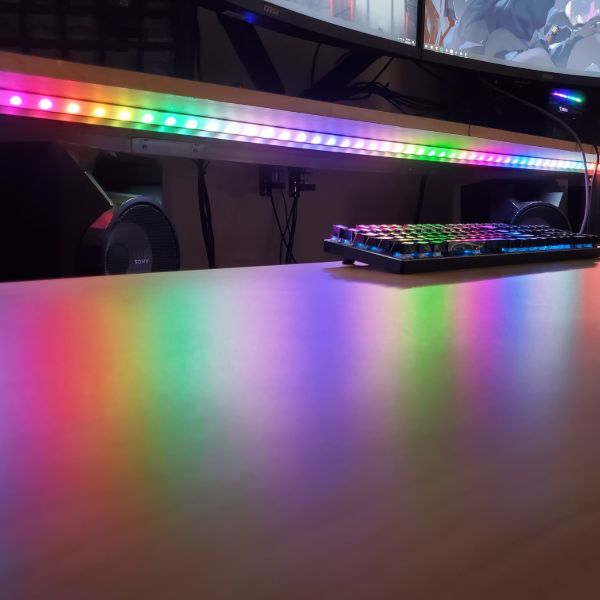
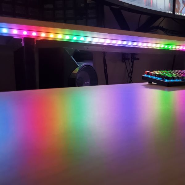
The last thing I’ve got on my mind is the fact that when all the lights are full bright white, voltage drop occurs and the lights yellow and become a warmer shade. I’m not sure how to approach this other than just adding a secondary power injection to the lights on the far end of the strip. Turning up the source voltage might work but there will still be a relative temperature dip, and that has a higher risk of damaging the strips
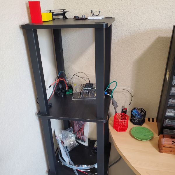
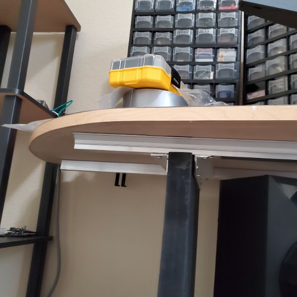
Along with all this, I need to pick a spot on the desk somewhere to put an enclosure that will hold both the PSU and the uC controlling the lights. The uC has to be WiFi enabled, so I was thinking an ESP32 or even just the Raspberry Pi long term. The only issue with that is, I want to run Home Assistant on the Raspberry Pi and it requires a hard ethernet port. I only have one running all the way upstairs for my computer, so the alternative would be to purchase PoE adapters and run either of those to the Raspberry Pi, but that seems a little excessive when I could just use the ESP32 local to the lightsbox and then keep the Pi on top of the Router.
The PSU doesn’t have a female AC cable port, so I’m probably going to have to buy some of those snap-in ones and then design and print a box with a hole that size and shape, and a rocker switch. Just like ATX Power Supplies. But I’ll also need some pin exposure and some USB port Exposure in the case for the ESP32’s IO. I’m pretty sure you’re not supposed to connect a USB port and a Vin pin at the same time, so I would need a switch to disconnect the Vin pin that I can flip before connecting the USB port. That’s a small concern but potentially nontrivial
Since I’m using JST connectors, I could probably design the case to have four ports for JST connectors in the side, and have those connect internally to the ESP. That seems like the most elegant way to design the box:
Lightsbox Enclosure IO
AC Cable In
MicroUSB In
4x JST In
Removable Lid for debugging
Small breadboard for ESP32 Circuit OR ESP32 Circuit on protoboard/PCB
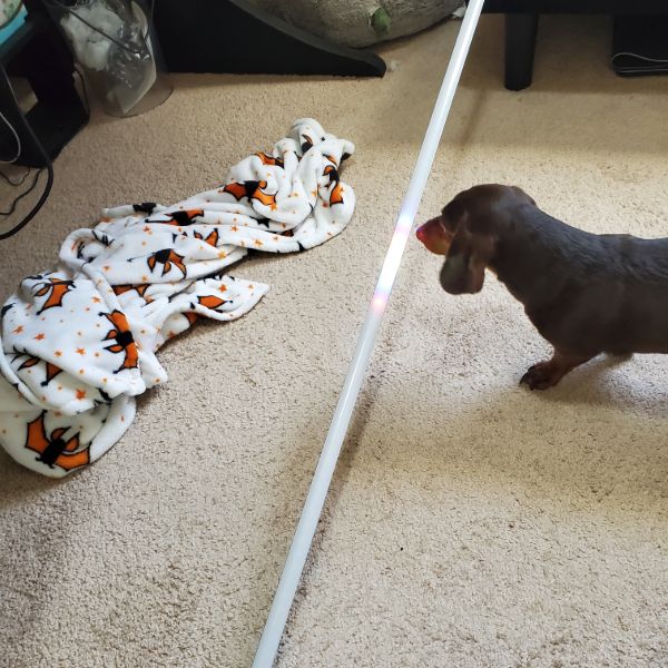
I’m not quite ready to understand the library in depth, but if I can write a simple program to keep all the lights white, or some other color, that’s good enough for me.
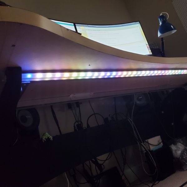
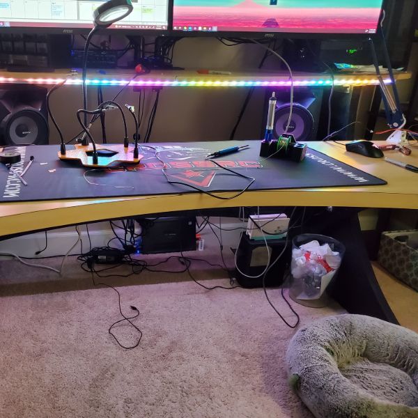
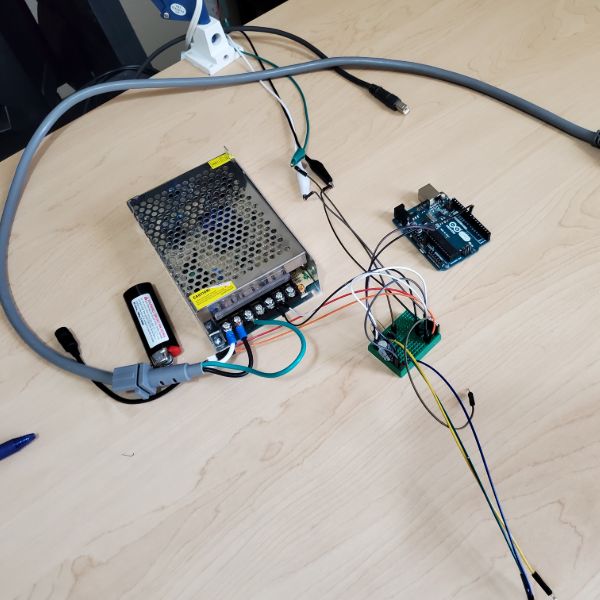
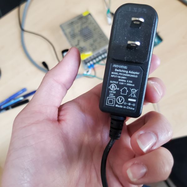
Some good news is that after switching fromt he 5V 2A wall wart adapter back up to the 5V 12A Power Supply I bought, the voltage drop light warming is basically a non issue. I think the shade shifts a little bit but it’s nowhere near as noticeable
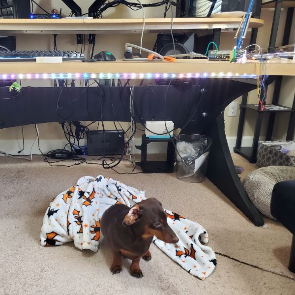
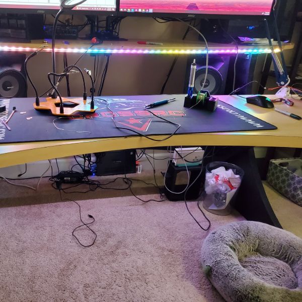
Spent about an hour just staring at the setup. I’ve got some plans for how to finish the mounting but I need an extra hand to get there
Next Steps
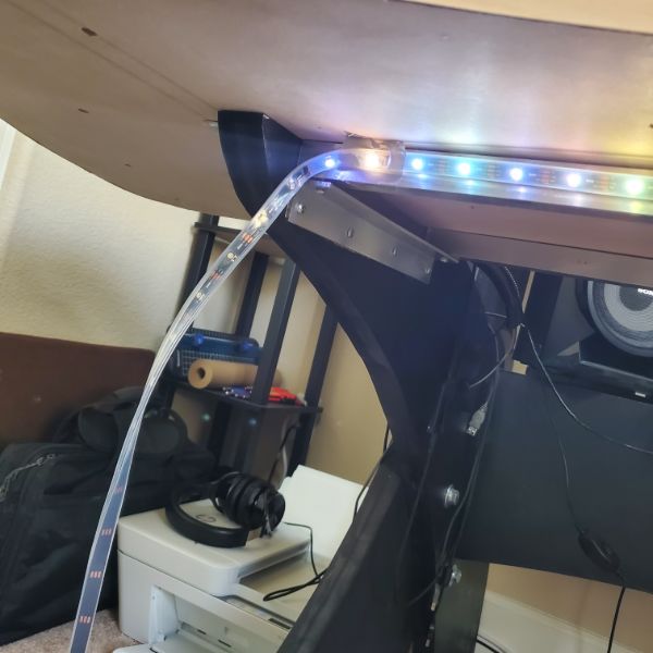
Finish Mounting backside rails, with diffusers and cut strips
Cut and solder wire adapters to length with installed rails going back to upper desk box spot
Confirm all 4 strips work on existing circuit, 1 PWM signal
Design a box to contain the uC, PSU, and board
Finish a more permanent installation with the box and some cable management
Reprogram the Arduino
Re-reprogram the Arduino when a pattern change is desired
Wait until Breadnet 4 is set up, then swap the Arduino for an ESP32 controlled via MQTT
Rigging
Need some names for things
Right Angle Strips – Turners
latch Clamp bridge connectors – Bridges
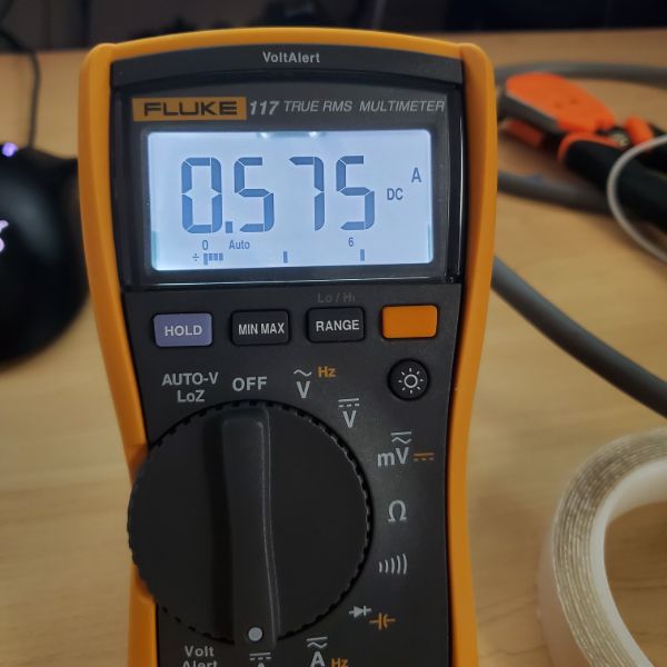
Going to create a cable harness for testing. It’ll use a bridge to connect to the LED strip and on the other end of the bridge, a turner can be exposed to test DC voltage and read the PWM signal on the scope.
After that though, a better harness would be one that can supply the power and signals, rather than opening a trivial port to measure them (that already exists on the strip)
That’s what the JST connectors are for after all.
I’ll clamp down a female JST ribbon into the Bridge, and with the male JST I’ll solder some pins that can be strapped over to the PSU and Arduino. That way I can use the same harness for testing strips of 10 LEDs and full reels
JST pin leads can be made to fit under the Bridge’s clamps, but the insulation prevents the bridge latch from closing
After stripping the pin leads, they can’t be coerced into staying under the clamp, mainly because the individual wires’ adhesives are no longer connected. It seems like it’ll be easiest to just use one of the turners to create a solder pad point for the JST to connect to
Soldered together the harness, but now I need to cut a new strip of 10 LEDs. The strip has directionality, and the front of the existing test strip already has a fixed harness and the terminal waterproofing insulation, so I’m going to leave that one as is and make a second one. This will also be useful next for parallel signaling tests
There is a bit of internal friction when it comes to pulling the strip out of the silicone sleeve, but it’s not difficult at all. I’m guessing it’s a lot harder to put back in though.
Connected both 10 LED strips in parallel. As I expected, the strips simply synchronize as they’re both receiving the same 10-strip expecting signal.
This means that I can rig it such that the upper and lower desks have the exact same sequencing. And there can be two data lines working off of the same Arduino. To run two separate data lines is going to require some more creative programming than the example codes are going to provide though. I don’t think it’ll be that difficult for the Arduino to manage 2 concurrent PWM signals…
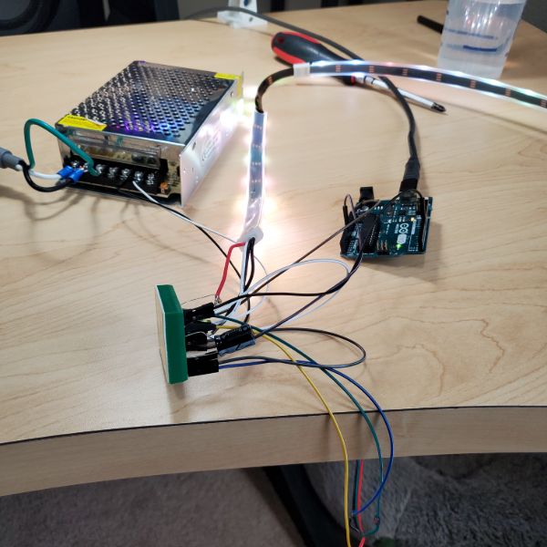
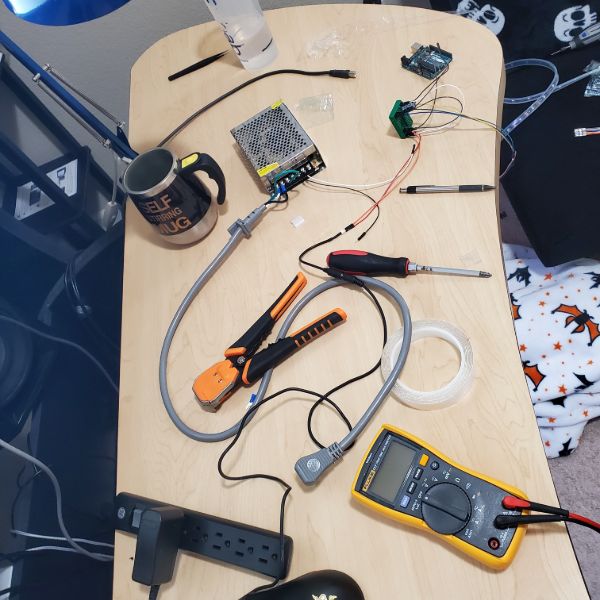
Connecting the main strip means setting up the 5V 12A DC Power Supply I bought.
I didn’t realize it didn’t come with an AC cable port, which means I have to screw down a spliced 3 wire AC cable into its terminals. Thankfully I already had one ready, but this also means I’m going to have to get creative with how this thing is housed and powered. I might end up buying my own AC cable female port and then embedding it in the 3D Printed hull of the Mega Lights Controller
I connected Test strip 1 to the main strip using a Bridge and started upping the light count. I can tell the programming updates when the lights blink onto a different color (using the Animation for fading). The limit seems to be around 80. Once I increase it past that, the Arduino takes the programming, but the behavior of the lights doesn’t change. Thankfully, I only need to run 60 LEDs at once on a chain, max. So it looks like that limitation isn’t really an issue, though it is inconvenient.
I changed it from the fade animation to the cyclone where it bounces back and forth and I was able to get it to chase all the way down to the end of the strip. But it has the same problem with counting the LEDs. There’s only about 140 on this piece, but it wouldn’t reach the end until I upped it all the way to 190. It seems like it might be counting some LEDs twice or something. There’s no glitches in the animation, so I’m guessing it’s just a software issue. It’s pretty confusing. I’m guessing the fade animation has a lot of information, since it’s constantly updating every LED in the chain, whereas the cyclone one only updates about 6 at a time
Software Test
The Default Neopixel library actually can’t work with the SK6812RGBW strips because they are only for RGB, so the instructions get corrupted as they’re passed on from the Arduino.
I’m using NeoPixelBus, which is a modified library that says it has support for the SK6812, and the sample codes are only 2 in number but they work fine. So this is something to go off of for now.
There’s only 10 lights. When I set the light count to 11, the 9th turns on, when i turn it up to 13, the 10th turns on. When set to 10, only 8 turn on. Strange
Turns out I was using Pin 13 and Pin 13 isn’t PWM, so moving it over to pin 9 solved that problem QUICKLY
Example “NeoPixelRotateLoop” is the best one to work off of so far.
I’m going to have to learn these things in pretty serious detail
“NeoPixelAnimation” Also works well
I need to test controlling two strips in parallel on the same data line, but with different lengths
apart from all the timing functions and stuff that’s the most important thing towards how the hardware will get wired
“NeoPixelCyclon” is my favorite by far
NeoPixelBus Library Dive
https://github.com/Makuna/NeoPixelBus/wiki
Might have to learn more about OOP for this
Want to take my time and really understand how to control these lights
LED Strip Research / Breadnet Project
Lab stuff, I have been kind of avoidant and dreading diving into the power supply. I feel like I don’t have enough time to get through the whole power supply series in just 2 weeks. Along with the Synth that I added on. If the Synth gives me as much trouble in layout as it did in Spice then I’m going to have an issue.
And if the Power Supply gives me as much trouble in either Spice or Layout as the Synth did in Spice, then I’m going to have another big issue. So I’m just generally not looking forward to getting started very much, so I spent a day researching some other stuff. Printer Upgrades, Desk Upgrades, Anti-Static for my chair, etc.
BOM
Parts will cost around $300
These aluminum channels are super expensive, so it’s in my best interest to go find the spares, if I didn’t throw them away.
But honestly, they looked super shoddy being constructed out of 1m segments
I might just drop the extra cash to get them 2m
Ideally, I would just buy 4 x 2m LED Strips, but that doesn’t seem to be an option
Even if I bought 7m at $18/m, that’s still $126, and then they look super shoddy and patchworked together. On top of multiple 10mm deadzones from adapters connecting together.
It looks like on two separate cases I’m spending an extra $50 just to make it look prettier
Comparison Video
https://youtu.be/QnvircC22hU
Power Consumption
Model
Voltage
Idle 0 LED
Single Channel per LED
RGB Channel Per LED
Single Channel, ALL 150 LED
RGB Channel, ALL 150 LED
PURE WHITE, ALL 150
SK6812
5
.83W
.05W
.148W
7.63W
14.4W
10W
Looking at the SK6812, as they are the only strip with a white pixel
Adafruit RGB Strip Product List
https://www.adafruit.com/category/183
Checking the data sheet, it looks like they have a max refresh rate of 30Hz
http://www.led-color.com/upload/201809/SK6812%20RGB%20LED%20Chip%205050%20Datasheet.pdf
Purchase Links
https://www.digikey.com/en/products/detail/adafruit-industries-llc/2828/5959337
https://www.adafruit.com/product/2824?length=1
Adafruit is the only reliable vendor for the SK6812 strips.
I’m looking at the black flex PCB with the minimal silicone sleeve. The 30/m strips run about $18/m. I am not sure how many meters I need though
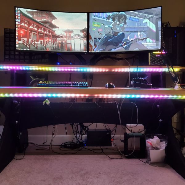
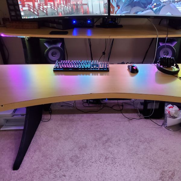
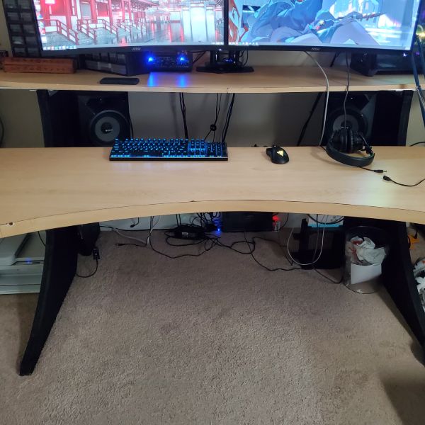
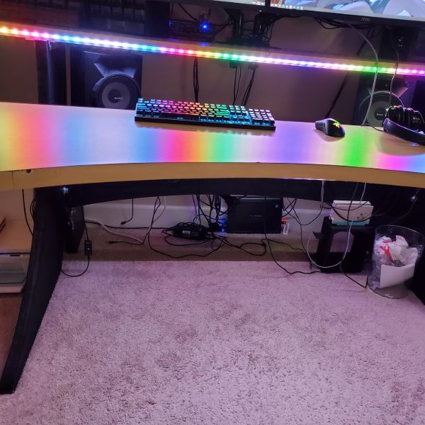
Desk is divided into Upper Desk and Lower Desk
Both Desks have two aluminum rails, and LED Strips go on the out-facing sides for both rails for both desks, so four strips in total
Upper Desk Rail Length: 1.95m
Lower Desk Rail Length: 1.46m
Total Length to Cover: 6.82m
SK6812-RGBW’s are only in stock in 1m and 5m variants. I’ll need 2x5m
Project Steps
This whole thing should probably be a part of a larger project of setting up the Smart Home in earnest.
Which would involve me learning more optimal MQTT, Learning the ins and outs of Node-RED and HASS. Connecting my 3D Printer to the Breadnet
Some Security Oriented work
And then setting up a logging database like a weather station that can be repurposed into crickets in the future
Also includes ESP32 Over-The-Air Updates
Also Includes the Python GUI project for the mega lights
So
MQTT Dive
Node-RED Dive
HASS Dive
Weather Station
Mega Lights
Mega Lights GUI
ESP32 OTA Updates
OctoPrint
Network Security
ESP32 Low Power Deployment
Sounds like about 1 full month’s worth of work. So I’ll save that for later, after I’ve finished the 6 month to FPGA bootcamp
Wiring
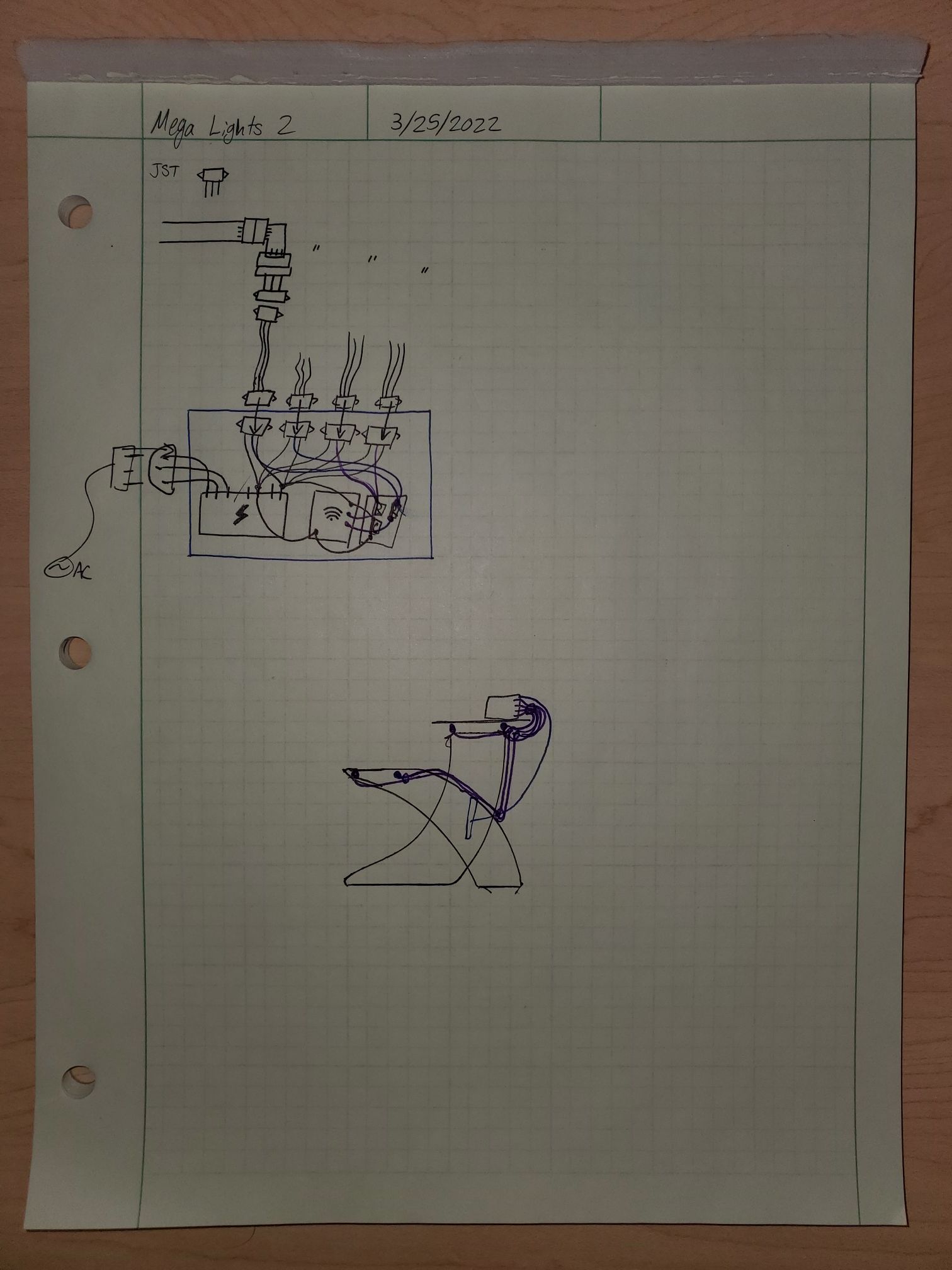
I’m thinking I’ll have all the wires on the right hand side of the desk.
From the front-lower strip, I’ll run a mesh cable sleeve like the one I used on the 3D printer along the underside, collecting the back-lower strip, and then running down the underside of the inner leg.
For the upper strips, I’ll also have the cables connect on the right hand side, going from front to back
From there, I’ll have the lower desk mesh sleeve run back up and meet up with the upper desk sleeve, and connect them using a Y-adapter into one mesh sleeve.
Then I’ll run that Mesh Sleeve to the PSU/uC combo.
To minimize cable management, it seems like it would be best to keep the Power Lines and the Data Lines terminal in the same location, so the ESP32 and the PSU are going to have to be in the same place
Power Consumption
30 LEDs/m
6.82m
204.6 LEDs
0.148W/LED
204.6 LEDs x 0.148 W/LED = 30.3W
30.3W @ 5V = 6.1A
Conclusion: Get a 5V/12A PSU
Mounting
I’m thinking about mounting the power supply on the underside of the upper desk on the right hand side, but I’m not sure that’s the smartest approach.
If I’m using a ESP32, The input voltage should be 3.3V-3.6V, but it has a regulator to handle 5V, or up to 6.5V I think.
The input output pins are NOT 5 Volt tolerant.
I think the safest approach would actually be to use the 2nd buck converter from the pack of 2 I bought for the 3D Printer, and set that to ~3.5V so the ESP has a buffer and a layer of extra regulation. Is that how power supplies work? Not sure. But I’m pretty sure that’s safer than powering the ESP32 directly from the PSU.
So if I’m putting an ESP32 and a PSU and a Buck Converter all in the same place, it wouldn’t be very convenient or elegant to mount all that on the underside of a piece of wood 4 feet off the ground.
I’m thinking the best option would actually be to run both cable mesh sleeves down to the floor and then just fashion an enclosure for the 3 Devices.
In that case, it would be simple enough to print an enclosure for everything.
Dimensions of the PSU are approximately that of Carl Jung’s Man and His Symbols
6″x4″x2″ roughly
6.26″ x 3.86″ x 1.65″ exact
Putting it in a 3D Printed Enclosure on the floor would also allow me to skip the whole Y adapted Cable Mesh Sleeve Problem as well.
This would also be a good opportunity to put my modeling and printing skills to good use in an electronics project for the first time
System Scheme
4 RGB LED Strips
Power Connection to PSU
PSU Powered From Desk Power Grid
Data Connection to ESP32
Look into OTA Uploads for ESP32?
ESP32 using NeoPixel Library
Connected to Breadnet via MQTT
MQTT hosted via RPi using HASS
ESP32 receives commands over Breadnet-MQTT via a Python Desktop GUI
PC
There are also RGB LED Strips specifically for PCs that can plug into slots on the MOBO, if that’s an angle I want to take. I kind of like it how it is now though.
If I’m going to put any more money into the PC, it’d be for a Noctua Intake/Exhaust Fan since there’s no net airflow betwen the PC and the room
https://youtu.be/8guzWUeQ3FQ
Future Upgrades
Eventually, I could replace the PSU with a 5V 12A one that I designed myself, but I’m not sure how far away that could be.
I’m also thinking about trying to sync it with keyboard presses or with audio
At minimum though, I want to create patterns that can be called at the press of a button off of the GUI
Ideally, I’d have individual control over the LEDs, which would mean the GUI would have a visual representation of each LED’s current status. From there, I could select an individual LED and set its color