
3/28/2022 – 4/10/2022
Mega Lights 2 Finished: https://youtu.be/PCQ9rvlqjPA
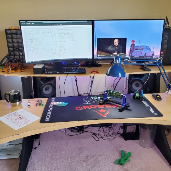
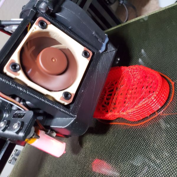
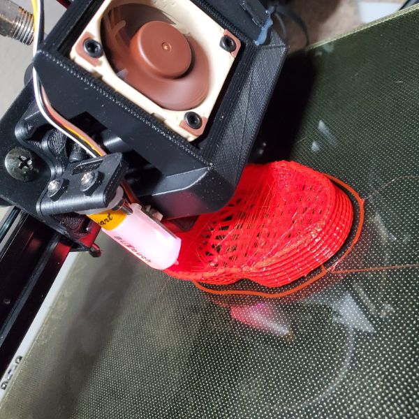
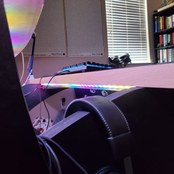
Summary: Objective this round was to build a prototype lightsbox, design the housing for the final lightsbox, solder together one of the Synth PCBs and make sure it works, and then work on the housing and front panel for the synth. A couple things pushed me off course. First, my 3D printer is still notoriously unreliable even after all the work I put into it. When it works it works great but it’s just too inconsistent, so I finally decided to drop some $$$ and ordered a Prusa i3 MK3S+, since it seems to be one of the best printers for consistency/reliability.
Next sprint will be reading AoE and setting up some software stuff. Less building and more research, designing, and writing. Not as many flashy pics like this one.
I also played with the idea of building an Autonomous FPV drone. Little RC plane with some telemetry, GPS, transceiver devices, and a camera. Researched GNC engineering and everything that goes into Inertial Navigation Systems. Engineering together a plane that can fly itself should cost around $500 to the standard I would want to do it at. Something to consider later on.
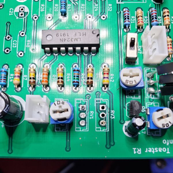
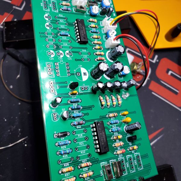
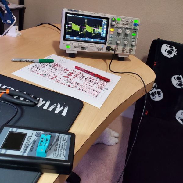
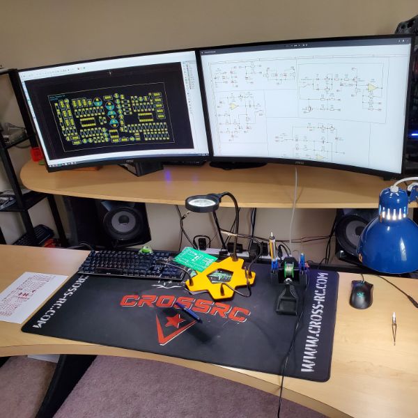
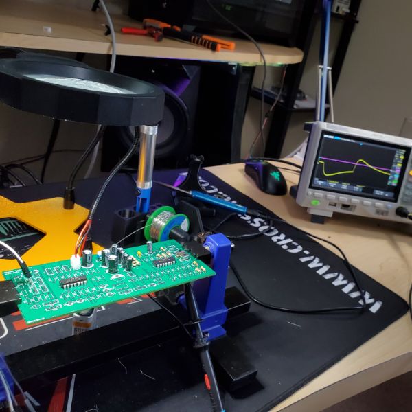
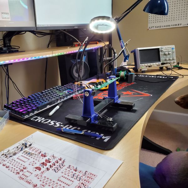
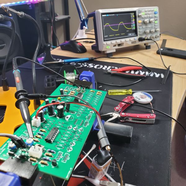
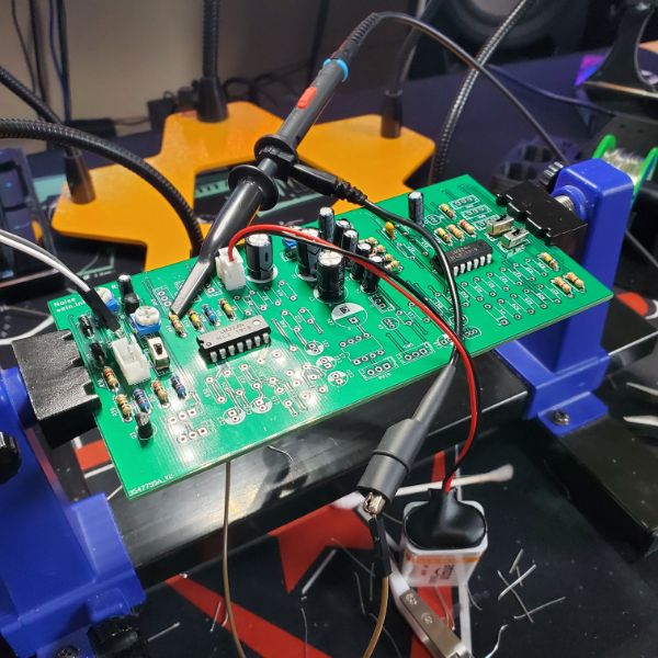
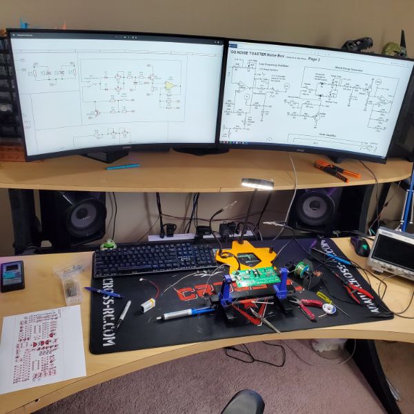
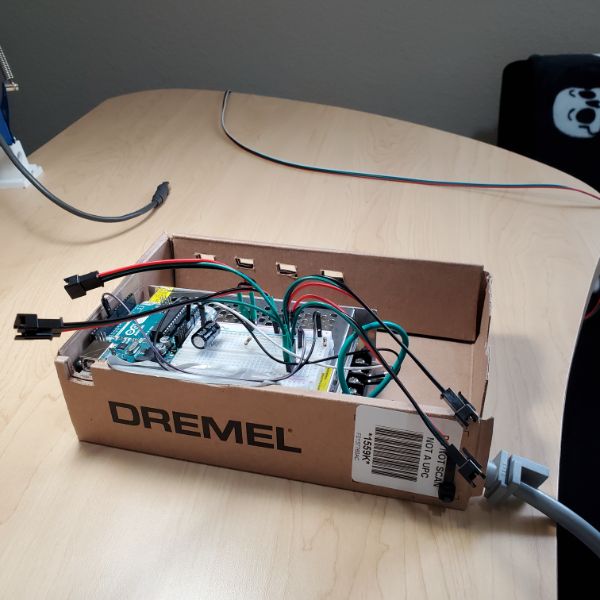
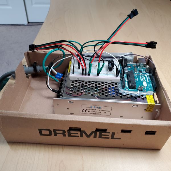
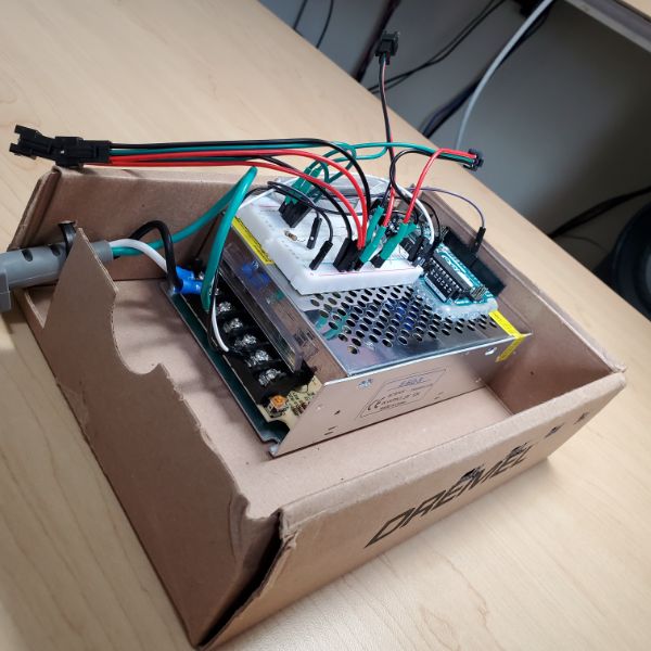
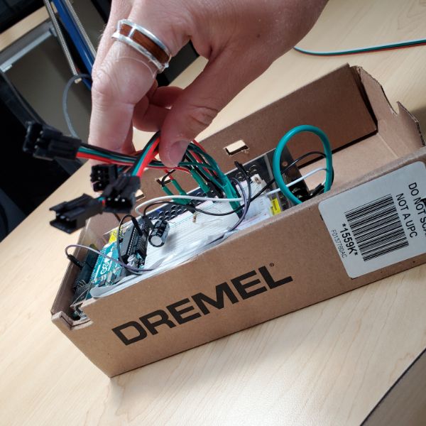
I was able to get the prototype lightsbox going, and have some early designs for the front panel, but since the printer isn’t working there’s not a whole lot I can do. Soldering together the Synth PCB was really gratifying because it worked first try! 🙂 I did find one error in the schematic, but not in the routing/circuitry of the board. Two resistors should be flipped vs what the schematic says to do. I also watched some videos on proper soldering and surprise surprise, I solder like a wild animal (lol) so I’m going to buy some equipment to do this stuff a little better moving forward
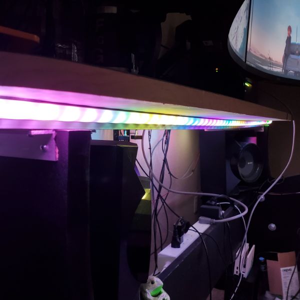
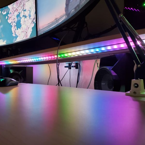
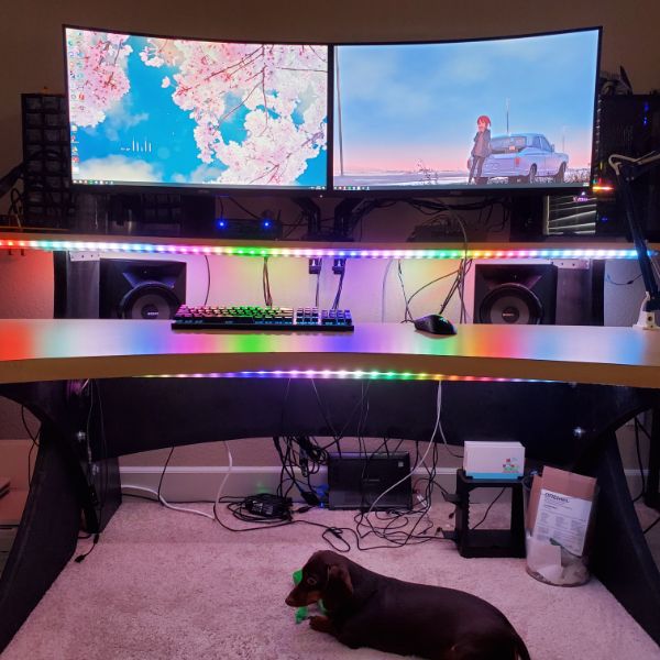
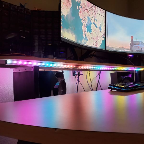
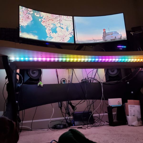
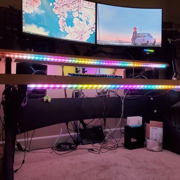
Lights are pretty reliable and I’m happy with them for now. Once I shift into software mode again they’ll get some more love but they’re doing everything I need them to right now.
The PCB version of the synth functions better than any previous breadboard version I’ve made. Much less signal interference and about 10x easier to use. I’m looking forward to getting this thing into a box so it can be another 10x easier to use.
Between the 3D Printer failing, and me taking a sudden research dive into GNC, and some other stuff, I pivoted around a lot this sprint. I spent the second week reading Art of Electronics, and it’s pretty gratifying. Since I have to wait for the printer for another 2 weeks, I’m probably going to spend a lot more time reading AoE in the near future. I want to get through that book cover to cover before the end of the year. I just finished chapter one. I also have some other project ideas once the new printer gets here.


Gorilla
Gorilla!
Art of Electronics
Table of Contents
Chapters
ONE: Foundations
1.1 – Introduction
1.2 – Voltage, current, and resistance
1.2.1 – Voltage and current
Voltages are what you apply to cause currents to flow
Voltage is the cost in energy to move a unit of charge from a lower potential to a higher potential
Nanovolts and Megavolts are rare
Current flows from positive voltage to negative voltage, even though actual electron flow is reversed
Voltages are applied ACROSS things. Currents go THROUGH things
Voltages require two points, currents require one point
We Generate Voltages, and then we produce currents by placing those voltages across things
KCL – The sum of currents in equals the sum of the currents out
KVL – The sum of voltage drops from point A to B is equal for every possible route
P = VI
Instantaneous Power is different from Average Power
1.2.2 – Relationship between voltage and current: resistors
A. Resistance and Resistors
The relationship between voltage and current is The Heart of Electronics – The name of the game is to make and use gadgets that have interesting and useful I-vs-V characteristics
Thick enough wires mean voltage drops will be negligible
R = V/I
Resistors usually come in three types
Metal Oxide Film
Metal Film
Carbon Film
Resistors are characterized by specs like
Power Dissipation
Physical Size
Tolerance
Temperature Coefficient
Noise
Voltage Coefficient (R’s dependence on V)
Stability with Time
Inductance
Roughly speaking, resistors can be used to convert voltages into currents and vice cersa
B. Resistors in series and parallel
Putting two resistors in series will always result in a larger equivalent resistor
Putting two resistors in parallel will always results in a smaller equivalent resistor
Resistor Value shorthand
2.2kOhm = 2k2
4.7MOhm = 4M7
10Ohm = 10R
2.2Ohm = 2R2
200Ohm = 200R
Shortcut 1: to lower the value of a resistor by 1%, connect a resistor 100x as large in parallel
Shortcut 2: The resistance of n equal resistors is the 1/nth resistance of the individual resistors
A mark of good circuit design is insensitivity to the precise values of the components
I = GV
G is Conductance
C. Power in Resistors
P = I2R
P = V2/R
D. Input and Output
Inputs are usually voltages
Outputs are usually voltages
They can be currents though
H – Transfer Function – The ratio of measured output divided by applied input
1.2.3 – Voltage dividers
Voltage Divider
Input Voltage, Output Voltage
“Load” on the output
Amplification is defined as when the output is larger than the input
Potentiometer – Adjustable Voltage Divider
1.2.4 – Voltage sources and current sources
Perfect Voltage Source
Two Terminals
Fixed Voltage Drop, regardless of Load Resistance
A Real Voltage Source can only supply a finite max current
Voltage source likes open circuits, hates short circuits
Current sources likes short circuits, hates open circuits
Perfect Current Source
Two Terminals
Constant Current through an external circuit, regardless of any load resistance or applied voltage
To do this it must be capable of supplying any necessary voltage across its terminals
Real Current Sources have a max output voltage compliance they can output in order to keep up with demand
Voltage sources have a real life equivalent in batteries
No physical analog for a current source
1.2.5 – Thevenin equivalent circuit
Any mess of batteries and resistors can be mimicked with one battery and one resistor – This is Thevenin’s Theorem
You obtain the Thevenin Equivalent Resistance and Voltage of a circuit and model it that way
You can get these numbers by calculation if you know what the circuit is, and by measurement if you don’t
You measure the Thevenin Voltage just, measuring the open circuit output voltage
To get the Resistance, you short it, and measure the current that passes through, use the voltage to back-calculate the current.
A. Equivalent Source Resistance and Circuit Loading
A voltage divider is not a very good battery because its output voltage drops severely when a load is attached
Attaching a load resistor causes the voltage divider’s output to drop
The thevenin resistance of the voltage divider in this case is a “Source Resistance”
Circuits that have output terminals can be thevenin’d to get their Source Resistance, or “Output Impedance”
Circuits that have input terminals can be thevenin’d to get their Input Impedance as well
Some circuits have both inputs and outputs, like filters
“Stiff” is used to describe something that doesn’t bend under a load. Meaning, its output characteristics don’t change much if the load changes
You want a voltage source with the smallest possible internal (thevenin equivalent) resistance
If you attach a load so small that its resistance is less than or comparably to the source’s internal resistance, the output will reduce considerably. You want the load resistance to be much higher than the source resistance
B. Power Transfer
These things all mean the same thing:
Source Resistance
Internal Resistance
Thevenin Equivalent Resistance
When R_load = R_source, that maximizers the power in the load for a given source resistance
In transmission lines, it’s importance to “Match Impedances” and set Rload = Rinternal to prevent signal reflection and loss of power transmission on the signals
Emphasizing again: Circuits are ordinarily designed so that the load resistance is much greater than the source resistance of the signal that drives the load
1.2.6 – Small-signal resistance
1.2.7 – An example: “It’s too hot!”
1.3 – Signals
1.3.1 – Sinusoidal signals
1.3.2 – Signal amplitudes and decibels
1.3.3 – Other signals
1.3.4 – Logic levels
1.3.5 – Signal sources
1.4 – Capacitors and ac circuits
1.4.1 – Capacitors
1.4.2 – RC circuits: V and I versus time
1.4.3 – Differentiators
1.4.4 – Integrators
1.4.5 – Not quite perfect…
1.5 – Inductors and transformers
1.5.1 – Inductors
1.5.2 – Transformers
1.6 – Diodes and diode circuits
1.6.1 – Diodes
1.6.2 – Rectification
1.6.3 – Power-supply filtering
1.6.4 – Rectifier configurations for power supplies
1.6.5 – Regulators
1.6.6 – Circuit applications of diodes
1.6.7 – Inductive loads and diode protection
1.6.8 – Interlude: inductors as friends
1.7 – Impedance and reactance
1.7.1 – Frequency analysis of reactive circuits
1.7.2 – Reactance of inductors
1.7.3 – Voltages and currents as complex numbers
1.7.4 – Reactance of capacitors and inductors
1.7.5 – Ohm’s law generalized
1.7.6 – Power in reactive circuits
1.7.7 – Voltage diiders generalized
1.7.8 – RC highpass filters
1.7.9 – RC lowpass filters
1.7.10 – RC differentiators and integrators in the frequency domain
1.7.11 – Inductors versus capacitors
1.7.12 – Phasor diagrams
1.7.13 – “Poles” and decibels per octave
1.7.14 – Resonant circuits
1.7.15 – LC filters
1.7.16 – Other capacitor applications
1.7.17 – Thevenin’s theorem generalized
1.8 – Putting it all together – an AM radio
1.9 – Other passive components
1.9.1 – Electromechanical devices: switches
1.9.2 – Electromechanical devices: relays
1.9.3 – Connectors
1.9.4 – Indicators
1.9.5 – Variable components
1.10 – A parting shot: confusing markings and itty-bitty components
1.10.1 – Surface-mount technology: the joy and the pain
Additional Exercises for Chapter 1
Review of Chapter 1
Resources List
Monty Choy Hardware Interview Questions
1
Digital Design HQ Discord #Resource Dump
2
EEVBlog Power Supply Design Series
3
Intel FPGA Technical Trainings
3
Digikey intro to RTOS
4
Digikey intro to FPGA
4
Digikey intro to KiCad
4
FesZ intro to LTSpice
4
Tutorial Sites
Asicworld
ZipCPU
Nandland
cplusplus
Practice Problems for Hardware Engineers.pdf
FPGA4Fun
Nandgame
HDLBits
EDAPlayground
FPGA4Student
Bitsolver
5
Art of Electronics
5
Automate Boring Stuff with Python
6
C++ for Embedded Systems
6
3D Printing Dive
7
FreeCAD Tutorials
7
Timeline
Original Plan
New Plan
January
A
3D Printer
B
3D Printer
A
3D Printer
B
3D Printer
February
C
Power Supply
D
Power Supply
C
KiCAD/LTSpice
D
KiCAD/LTSpice of Synth
March
E
Power Supply
F
Interview Questions
E
Breadboard of Synth
F
PCB Routing for Synth
April
G
Interview Questions
H
Intel/Quartus
G
LED Strip Installation
H
LED Strip Backend
May
I
Tutorial Sites
J
Tutorial Sites
I
Power Supply
J
Power Supply
June
K
FPGA Projects
L
FPGA Projects
K
Interview Questions
L
Interview Questions
Interview Questions
4 weeks
Intel FPGA
2 weeks
FPGA Projects
4 weeks
Power Supply
6 weeks
3D Printer
4 weeks
C/C++/Python
Verilog
Art of Electronics
4 hr/day
4 hr/day
2.5 pages/hr
5 pages/hr
24 min/page
12 min/page
10 pages/day
20 pages/day
100 pages/sprint
200 pages/sprint
200 pages/month
400 pages/month
6 Months?
3 Months?
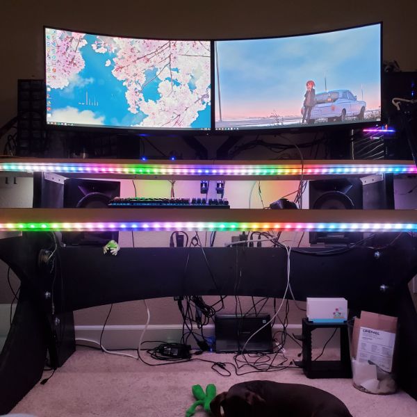
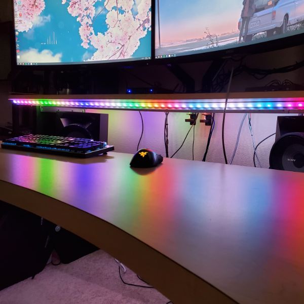
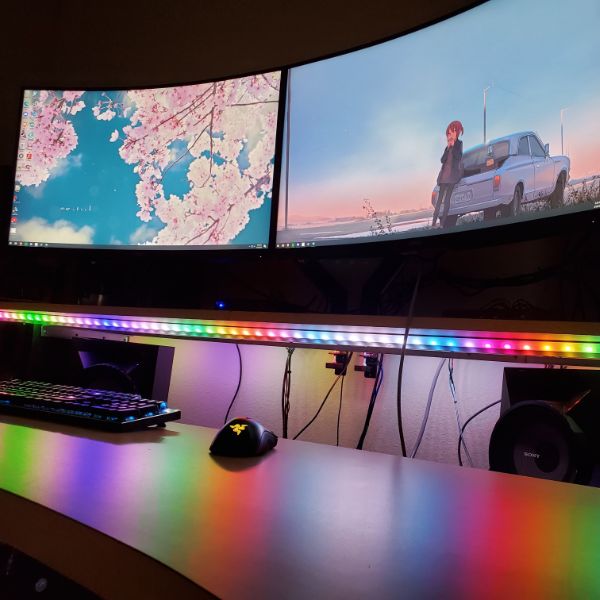
(3/16) Mom said my present should be arriving today. Bub asked me how much railing I need so I’m guessing she bought me my LEDs. Which is pretty exciting.
I’m thinking my lab sequence will be
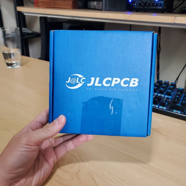
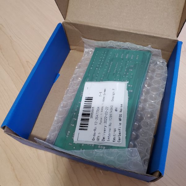
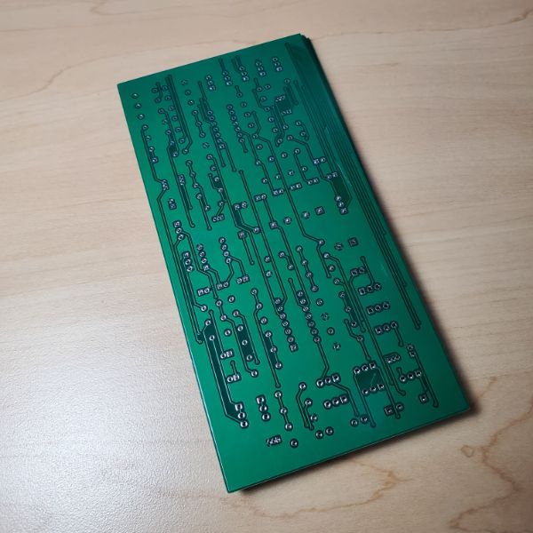
Synth PCB Layout, Order
1 week (this week)
Research how to install strips
1 week
Install Strips, set up backend
1 week
Assemble Synth PCB, Validate
1 week
Start Power Supply Design Series
I can tell I’m kind of avoiding the Power Supply Project
Synth
Order PCB
Solder
Model Housing
Design Front Panel
Polish
Mega Lights
Dive in NeoPixelBus Library
Some OOP?
VSCode/PlatformIO/Github Setup
Hardware Mounting on Desk
Setting up Breadnet IV
NodeRED, MQTT, Tkinter, etc.
Power Supply
Interview Questions
Art of Electronics
Map Interview Questions to Page numbers in AoE
Automate Boring Stuff with Python
Design Christmas Present
Sprint Objectives
Finish Mounting Lights
Full Control over 1 LED
Temporary Enclosure Designed, Printed, Installed
Cable Harness Complete, Safe
Synth PCB Soldered Together
Synth Front Panel Component Adapters Soldered Together
Synth Enclosure Sketched/Designed
Lightsbox Enclosure Sketched/Designed
Set up VSCode/Github again for future coding on lights
Pivoting to an Autonomous Plane Project
Mega Lights 2
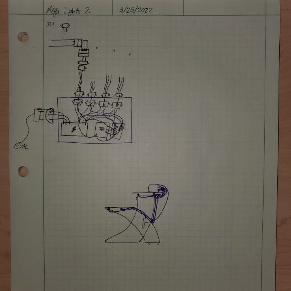
Order more JST-XH connectors (not plain JST)
Find a Female AC Cable Port for the box?
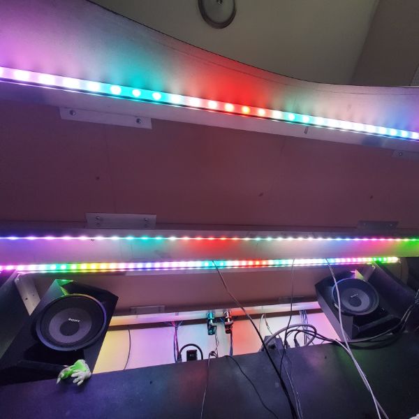
Back upper strip looks great, installing lower back strip now
Need to get a count
LIGHT COUNTS
UPPER DESK: 58
LOWER DESK: 43
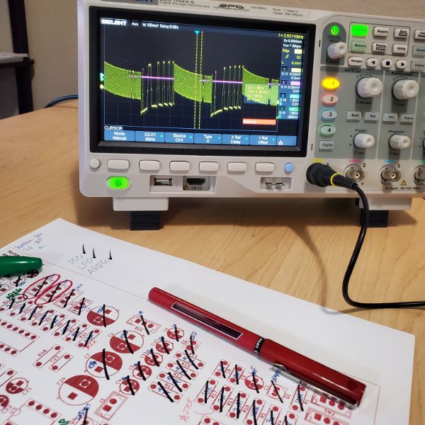
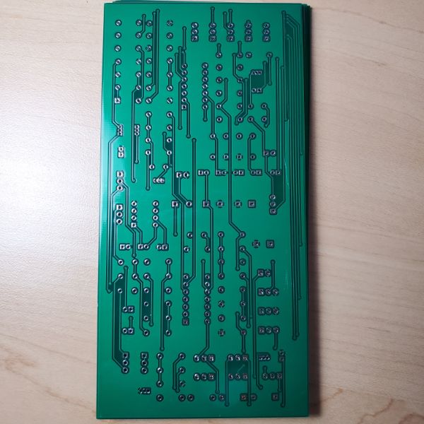
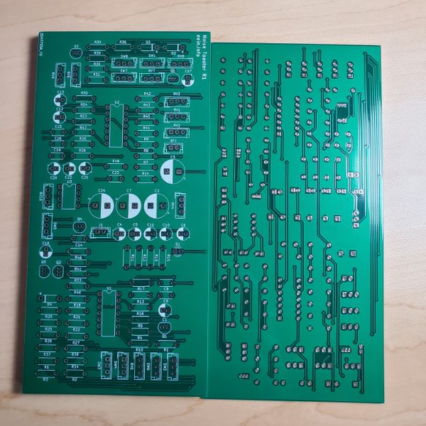
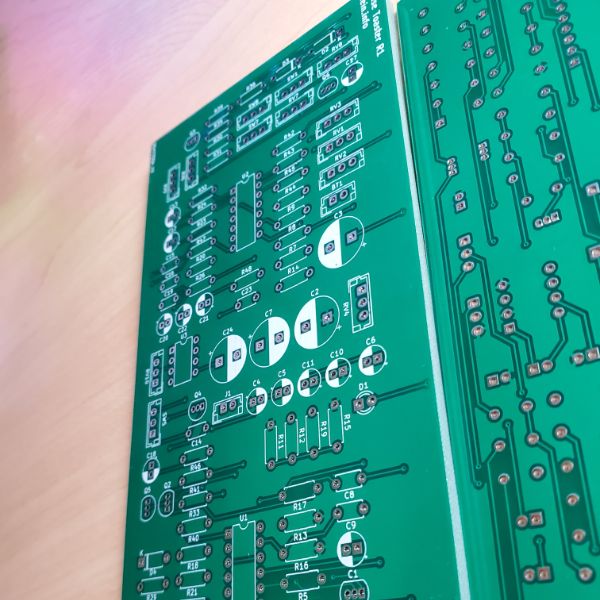
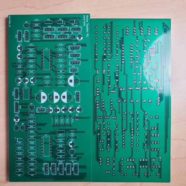
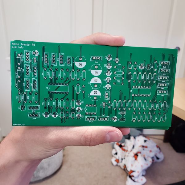
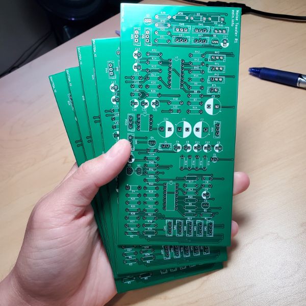
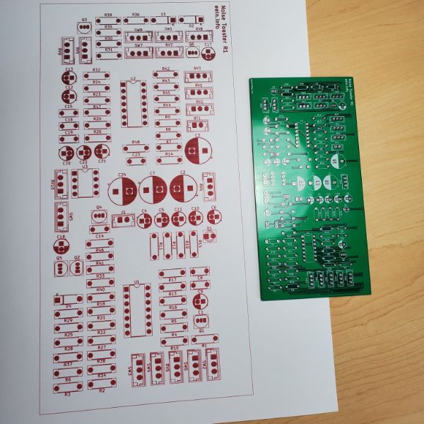
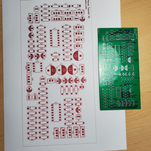
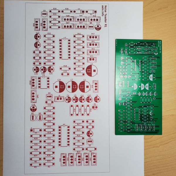
Synth PCB
Order Pots and Switches
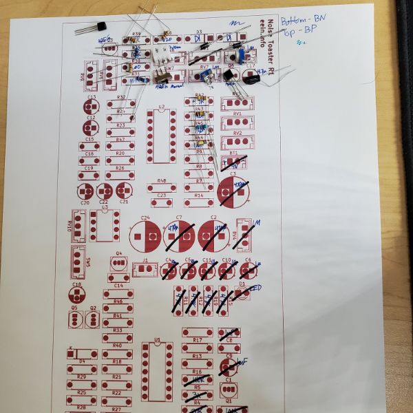
Soldering plan
Place Order, Print Papers, Set up Station, Pick Parts, Get Moving
Notes from E
Potentiometer
1M: 3
RV4
RV7
RV8
100k: 7
RV1
RV2
RV3
RV5
RV6
RV9
RV10
Switch List
Power Switch: 10
LFO Shape: 10
VCO AREG Input: 10
LFO Select: 11
AREG Repeat/Manual: 11
VCF Select: 11
VCF Source: 11
Totals
11: 4
10: 3
Angel suggested I print out an enlarged sheet of paper, sketch the values onto the zones, and then use that as a holder for all the part placements. Honestly a really good idea. I’m out of black printer ink at the moment though, so it’ll have to be in like, red or something.
I imagine picking out all these components several times over is going to be a huge pain in the ass. I’m guessing I’m going to run low on some stuff and have to order some new ones, especially for the later instances of the board
The JST connectors also need to be built out carefully, because if I miswire them stuff might not work as intended. The pins on the JST’s can be indicated on the piece of paper too, so that’s another point
I wonder how resistors are made, and if one could make an on-demand resistor printer machine. It could print values from 10-10M with some moderate tolerance rating like 5%. You’d punch it in like the coca cola freestyle soda machines and it would just grind and crunch for a second like a vending machine and drop out the custom fab resistor right there.
Something like that would probably be a little harder to pull off with capacitors
I’m not sure if I should use the pots I have access to now as a debug/test tool. It’d be a bit of a waste of the JST connectors, but also lets me fail without having to place yet another parts order in case I do mess up
Probably smart
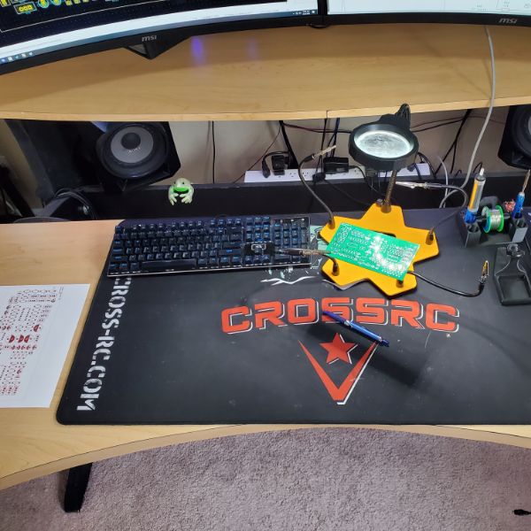
Lots of soldering today, my soldering stand is still dead in the water… Something to work on later
It just occurred to me that I could save myself an hour by buying some pre-crimped JST-XH 3 pin connectors. I’m not a big fan of buying my way out of problems but like, there’s 15 3-pins here. That’s basically a whole day of work
The connector sets come in sets of 20, so I think I’ll make this first board a test board, and then polish it later, or just solder together a second one
Which means I’ll connect these pots and switches as directly as I can, instead of trying to make a mock front panel
Assembly Notes
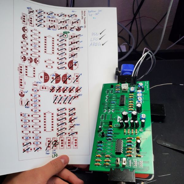
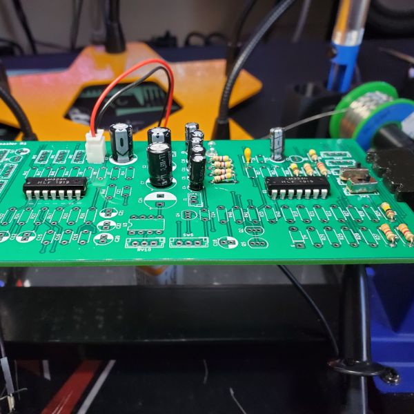
I think R13 and R14 are switched on the PCB layout, and I have no idea why, but that may explain the malfunction of the VCO
R13 adn R14 had their reference designators flipped on the schematic, which informed me as to the value of components. So the PCB had them in the correct position, but the schematic instructed me to reverse their positions, which created the error.
After flipping them back, I was able to get the VCO working perfectly.
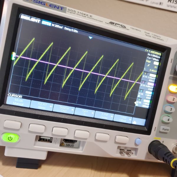
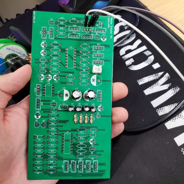
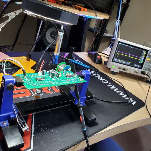
The entire synth is assembled now and it works pretty much perfectly. It’s way more functional and stable/less noisy than the breadboard synth. The only issues I’m having at the moment are, the speaker is absolutely destructively loud unless the volume pot is at like 3%.
I also noticed I’m still picking up some radio signals whenever my hand is in contact with the volume pot.
The AREG pots don’t seem to work exactly as I expect, but I think it’s because the pots are soldered directly on.
I had to disassemble and clean out the solder sucker, and now I can use that in tandem with the copper mesh tape for absorbing solder to desolder components pretty cleanly. That was always an issue before that prevented me from fixing mistakes, but now I can desolder and resolder as much as I want, so that’s nice.
I originally built out the PCB expecting to do a second pass, but it seems like it’d be easier to just desolder the switches I connected directly and add the JST connectors, and make this board the first rendition of the final product.
One thing I neglected to do in the board design was add screw holes to mount the PCB to the casing. I’ll either have to carefully drill them myself, or create a 3D printed snapping mechanism specific to these board dimensions
I replaced the 100k pot in the volume adjust with a 1M pot to try and get the thing to be quiet, and it sort of succeeded, but I noticed signal quality was much higher with the 1M pot, so I’m sticking with it.
I purchased JST-XH connectors off of amazon so I didn’t have to spend hours crimping, but it turns out I ordered JST-XH Mini connectors, so they’re not actually the same as the ones I’ve been crimping by hand, and the inconsistency drives me a little crazy, but the minis are actually more convenient for this case. Something to pay a little more attention to later
Housing and Front Panel Notes
I don’t think the housing should be any more than 5cm deep in total. I layed out 10 pots and 6 switches and I was able to get them all to fit cleanly on top of a blank PCB, so the dimensions of the housing don’t need to be that much bigger than that of the PCB itself, which is nice because this thing will be pretty compact.
Since I want users to be able to replace the 9V battery without having to expose themselves to the guts of the PCB, I’ll need to design a little 9V chamber in the back of the housing with the pull off cover and everything. That also means I need to buy a 9V battery holder as a part of the parts list for this thing.
with a 5-10cm depth for the housing, the length of the JST connectors I bought won’t be an issue. They’re around 6 inches long.
I still don’t know how I’m going to 3D print a front panel with labels for things. I keep thinking, this would be easier with a Laser Cutter. But I guess since I’m in the market for a new 3D Printer, I could always just get a dual extrusion upgrade and do a multicolor scheme. I have no idea how those things work though.
I’m guessing once everything is designed and assembled, the whole thing will take about 3 hours for picking and soldering parts, cutting leads, soldering pots, and mounting into the front panel. If I wanted to sell these things, I’d have to make it worth my time, so if there was any sort of volume whatsoever I would have to hire someone else to do them for cheap. In terms of parts, it’d be the cost of the PLA, the cost of the parts, maybe $5 max, then the cost of the JST connectors which are like $6 on their own. Then speakers and battery, maybe it’d be around $20-25 in parts for each synth. Discounting labor, I could probably sell these things for $30-60. I wouldn’t feel quite right selling this thing for as much as $60 though. Maybe if I could build more capable, more robust synthesziers, I’d feel comfortable selling something for $150-200 and that would be a more comfortable price point.
I do have books that could make me better at designing synthesizers. The main thing I don’t like about this thing is it’s so high pitched. I would want a synthesizer that could really RUMBLE. Also, how many people even want/need synthesizers? I feel like it’s more in the gadget/nonsense category if you’re not a literal professional. Maybe amateur musicians who want a unique sound
I could sell or just give one to itvlo and matt and I’m sure they would enjoy that.
Synth Enclosure
need to print a sheet that has pot
Designed a basic front panel layout for a 150mmx75mm sheet. But the printer doesn’t work anymore so, kms
3D Printer
3D Printer turns out, still garbage. Did some research, decided to buy a Prusa i3 MK3S+
It was about $800 and the lead time is 4-5 weeks, but it seems to be the best printer for long term consistency/reliability. At least, based on “Out of Darts”‘ review. He’s got a print farm with around a hundred of them and some with one million hours of runtime. A lot of reviews only look at part quality, construction, and print quality. I’m more concerned with the consistency of the tool, not the upper limit of what it can do
This means that I won’t be able to print the enclosures for the Lightsbox or the Synth for about a month. If I want to proceed with the plane project, that’ll have to wait a while too. I need something else to do in the meantime.
I can start working on the Power Supply, I can start setting up Breadnet, I can start a new software dive, or I can read AoE. I’m thinking AoE, but that’s not as glam for the website. Ultimately though, I do need to spend time devouring textbooks like that if I’m ever going to acquire some really expert-level technical knowledge.
I’ll finish soldering together the knobs and switches on the Synth and then pivot to AoE. That way when the printer does show up I’ll be ready
I also wanted to watch the EEVBlog videos on soldering and learn some advanced soldering techniques, but I think that can wait until the printer shows up and I design a better soldering station
Printer set to ship within a week of 4/25, so I’ve got about 3 weeks before I can print again
Soldering Guide
Tools
https://youtu.be/J5Sb21qbpEQ
Turns out the gold scrub is coated in flux when you get it
The wet sponge is helpful
Pay a premium for the thinnest solder you can get, so you have more control over the amount of solder added
Multicore solder has rosin core, which is a tree sap, which is the flux
Don’t get unleaded solder, it sucks. 63/37 Sn/Pb ratio is superior to 60/40 because it melts at one specific temperature. 60/40 has a plastic region and a band of temperatures at which it can melt
Some solder also has silver, which helps bond to silver coated SMT terminals
Keep multiple spools of solder wick on hand, you go through a lot of it, apparently
Magnification and good tweezers are essential for SMT work
Fume Extractors are ok, range is limited, sometimes it’s better to just have a fan nearby.
The lead fumes aren’t what get you, it’s the flux. BUT you should wash your hands after you solder. Don’t rub your eyes, etc. If you’re gonna do a lot of soldering, just wear some disposable gloves
The default conical tip is garbage, keep a finer precision tip for other stuff but get a fine Wedge tip for general purpose, it’s much better. Also check out Well-Tips for SMT
Be mindful of the set temperature, as the tip temp is regulated, but is immediately sapped away, so the rest of the iron provides
350C is good general purpose temp. If you’re working with something beefy like a heatsink, go up to 400C
You don’t really go above 400C. If you have sensitive components, you can go down to maybe 280
You can buy CLIP ON HEATSINKS for THT components… wow
Safety goggles for the splash. It can splash long distances
Hot Air Gun
Flux Pen
Solder Paste for SMT
THT Methods
https://youtu.be/fYz5nIHH0iY
SMD and THT, connectors, wiring, etc. basic principles are the same
Touch the tip to the pin and the joint first
If you put the solder on the tip first, you’ll see it smoke. That’s the flux burning away, so you’re not going to have a good time.
The flux cleans away the oxide layer off of the metal so they can bond
#1 – NEVER EVER apply solder directly to the iron
No extra flux is necessary for THT
Iron to Pad+Pin, wait a second, bring solder in on opposite side of pin, feed in, solder out, iron out
A good joint should not be a ball. It should be bright and shiny (leaded)
If its not nice and smooth, its craggy and messy and doesn’t flow through and balls up, that’s called a COLD JOINT. You can see them clearly on the opposite side as well. Stop SUCKING
The dandruff that you can scrape off from the solder joint is dried flux residue
Some old resistors will have oxidized legs that you’ll have to actually scrape clean in order to solder
“Forming Component Leads” – bending it right
Don’t trim multiple leads at once with the wire snippers. It puts stress on the solder joints and can crack them. A cracked joint can be worse than a cold joint
Iron tips are plated and that plating will erode over time. You should match the tip type to the solder type. unleaded solder will erode the lead-enriched plating on a tip designed for lead solder.
You can actually refresh the plating with some solder, contrary to #1. but this is not for making joints
Also contrary to #1, having a very small amount of liquid solder on the tip causes it to melt easier
Once the tip is no longer plated, throw it out, it will only create problems
Anti-Static Brush + IPA (Spray on or liquid) acts as electronics cleaner to clean off the flux residue/dandruff
It looks like a toothbrush
Don’t add too much solder and create a hershey’s kiss
Ground plane pads have thermal reliefs, where the hole isn’t connected all around the circle, since that would cause excessive heat dissipation into the ground plane
Conical tips have too little surface area of contact
Flux, Tip, and Solder quality are all huge. technique can’t compensate for bad tools
Flux comes in liquids, gels, pens, etc. If you were going for aerospace quality, you would apply flux to every single joint before soldering
Your iron has to touch both the pin and the pad for this to work right
For connectors, you can pre-solder the connector body, then tin the wire, and then bring the two together. This often produces more elegant joints than just feeding in solder during dual-contact
For large pads and thick heatsinks, get a bigger chisel tip and wider diameter solder
The un-contacted sides will cool off faster, so spread it all around, and then add more all around.
Don’t overheat the device though. Also, since it’s a large, high thermal capacitor device, it’ll remain hot for a while
A smaller chisel tip won’t be able to get the solder to flow for these larger pads, after the fact. same temp and all.
Summary
1. Good brand temp controlled iron
2. Good brand <0.5mm solder
3. Flux is everything. In solder and separate
4. Use the right tip. Chisel tip is best
5. Don’t bring the solder to the joint. Iron one side, solder to the other
6. Use the right temp. 350C is usually upper limit
SMT Methods
https://youtu.be/b9FC9fAlfQE
0402 component are very difficult and require magnification. It’s generally easier to just do 0603
Older pick and place machines can only do 0603 reliably. 0402 capable machines are less reliable, so the fabhouse might charge you more if your components are too small, stick to 0603
Multilayer Ceramic SMT Capacitors can be heat damaged pretty easily, so be quick
If you leave your iron on too long, the excess heat can actually pop the pad off. Be way of that
Tack and Reflow Method
Solder one of two pads first, then Tack the component down and reflow it so it sticks, then add the solder to the second pad.
This usually requires you to flip the board around since you’re right handed and stuff is small.
Also, most people will do this in a batch process type procedure
Check your work with a Jeweler’s Loop
Use a very small Chisel Tip on your iron, same principles apply, hit the pad, tin the pad a bit
For an IC with many pins, tin a single pad, use the tweezers and reflow the pad to set the IC, and once it’s set in place, just go ahead and solder the rest of the leads
It’s ok to short a few leads as you’re getting started on the tack and reflow, you can fix it later
It’s useful to use a flux pen on all the pads before getting a move on, it helps the solder take. The flux pen will be nowhere near as precise as the soldering iron, so just go nuts.
Flux Pin + Well Tip is based
You can do it with the chisel too if you just get a glob of solder on it and then drag
If you put too much or some stuff shorts, a dry drag can reflow the solder and cause them to gel and separate
Just rub the pen, fill the well, then drag the iron across the board.
You don’t have to drag across the pins, you can also slide in on them a handful of times until they’re all hit
Don’t apply a lot of pressure while dragging or you can lift the chip
You might short two pins, wick it and move on
For wicking, the stack goes joint-wick-iron
The wicking/well tip can actually also do a wicking move on solder bridges/shorts
Flux really helps, unless the components and boards are brand-spanking new and have zero oxidization
You can never have too much flux
Recommend doing the opposite corner as a second stabilizer first. Reflow as necessary to optimize positioning
Solder mask is absolutely essential for SMT boards, and it will prevent shorting between close pins
If you try to apply solder to the solder mask directly, it will blacken but it will never take
Don’t apply the solder to the iron, apply it to the tip or the pad. This can be difficult because everything is small
Guidance, Navigation, and Control
Components of GNC
https://www.aseifl.com/GNC–Identifying-the-Components-of-Autonomous-Systems-Engineering-1-11988.html
Scope
Guidance – all flight mission phases, including launch, rendezvous, and descent.
Navigation – system architecture, such as sensor selection, position/orientation determination software, and architecture trade studies.
Control – algorithms, vehicle, and control system requirements and specifications.
Mission planning – orientation design and planning, launch opportunity, and mission modeling and simulation.
Sensor hardware – design, build, and calibrate specialized sensors.
Functions
Attitude Control System
Controls pitch, roll, and yaw. These form attitude
Flight Path Control System
Determines flight path in real time in response to environment
Avionics Systems
Replace the human pilots in unmanned vehicles.
Type of sensors used depends on aircraft’s maximum operation range, conditions, and kind of info needed
Accelerometers
The heart of inertial navigation systems is an arrangement of accelerometers that detect changes in vehicular motion to aid in guidance.
Accelerometers measure distance in three directions: Range, Altitude, Azimuth.
Measured distances are compared with desired distances, and correction signals are sent to the control system accordingly
INS Facts
https://www.aseifl.com/Facts-About-Inertial-Navigation-Systems-You-Might-Not-Already-Know-1-11989.html
INS – Inertial Navigation System
Three important factors
Precision
Velocity
Balance
GPS is not necessary once in operation, but is necessary to set the initial position, velocity, and orientation of the vehicle. INS can provide pinpoint from then on
Uses Accelerometers and Gyroscopes and Microcomputers to process info in real time
Gyroscopes measure the sensor frame’s angular velocity relative to the inertial reference frame
The heart of the INS is the IMU
IMU – Inertial Measurement Unit
IMUs integrate the accelerometers and gyroscopes
Some IMUs also have magnetometers
INS vs GPS
GPS requires satellite transmission and a Ground Control Component
GPS systems require constant connection to the satellite system
INS are fully autonomous after init and are self contained, thus resistant to radar jamming
INS Advantages
Resistant to jamming and spoofing
Perfect for complex operations in land, sea, air, and space
Con: IMU calculation errors become more prominent with each new position calculation
This is corrected with occasional GPS upcheck
Components of Integrated GPS/INS Systems
https://www.aseifl.com/Built-for-Success–The-Components-of-Integrated-GPS-INS-Systems-1-10399.html
Sensor Fusion – an umbrella term, refers to all available information available in all conditions
GPS connection can be easily jammed by natural terrain, landscaping, and manmade methods
INS runs without external references. INSs house a CPU that ingests info from multiple sensors
Vision Aided Navigation
“Photogrammetry”
Some Computer Vision to navigate terrain and landmarks
helpful in GPS-denied environments such as tunnels
Gyroscopes
A spinning rotor that is suspended in a system isolated from external torque
Since the rotor wants to maintain initial axis of motion, the sensor can measure the change in orientation
Odometers can come too
How Resilient Navigation Systems Benefit Your Avionics in GPS Denied Environments
https://www.aseifl.com/How-Resilient-Navigation-Systems-Benefit-Your-Avionics-in-GPS-Denied-Environments-1-9943.html
A System comprised of an IMU, a GPS Receiver, and Sensor Fusion Software
Accelerometers, Gyroscopes, Microprocessors
The system calculates how it has moved through 3 dimensional space and then combines that information with latitude, longitude, and altitude to successfully complete its mission
The most important factor of the GPS/INS in your avionics is being able to trust that it works perfectly, every time
Multiple Micro-electromechanical systems – MEMS – fit into a device the size of a quarter, gyro, accel, processor
AHRS – Attitude and Heading Reference System – combines the IMU function with the ability to actuate on the attitude of the vehicle
RTOS Skill Tree
C Programming => Data Structure => Single Thread Application=> Linux => Multi Threaded Application => Embeded Linux => Mini RTOS => RTOS.
RTOS Layout
The best way to learn is to implement a RTOS. A good place to start is http://www.freertos.org/
Here’s a brief overview on RTOS for those that aren’t looking to commit to a book or code just yet. [Credit to Professor Jim Peckol at UW, this answer is based on my old notes from his class]
An operating system has to provide 3 essential things:
Task Scheduling – The scheduler determines which task to run and when a task will run
Task Dispatching – The dispatcher handles the necessary operations to get a task ready to go
Intertask Communication – This is the mechanism that handles how you exchange data and information between tasks and processes on the same machine or from other machines
These 3 essential things are what makes up the smallest portion of an OS called the Kernel.
A real time operating system is just a special purpose operating system. The ‘real time’ part of the name does not mean that the system responds quickly, it just means that there are rigid time requirements that must be met. If these time requirements are not met, your results can become inaccurate or unreliable.
So you want to use a RTOS when you need to monitor and control physical processes in a timely manner. The constraints you have deal with when using RTOS are tight scheduling, predictability, and robustness.
There are two kinds of RTOS:
Hard Real Time – System delays are known or at least bounded. Said to be operating correctly if the system can return results within any time constraints.
Soft Real Time – Critical tasks get priority over other tasks and will retain priority until the task is completed. This is another way of saying that real time tasks cannot be kept waiting indefinitely. Soft real time makes it easier to mix the system with other systems.
The other functions that the OS handles outside of the Kernel are:
Process management
Memory management
I/O system management
File system management
System protection
Networking
Command interruption
Unnamed Unmanned Autonomous Aircraft
Parts List
Part Name
Function
Price
PixRacer R15
Flight Controller
$199
Dragonlink Nano Receiver
Receives Telemetry
$98
6g analog servos
Attitude Controls
$22
generic GPS
Receives GPS data
$30
RunCam Split Mini
First Person Video
$69
TBS Unify video TX
Transmits Video
$39
HGLRC 1407 3600KV Motor
Propeller
$15
HGLRC 1407 3600KV Motor
Propeller
$15
BLHeli 20A ESC
Motor Controller
$15
BLHeli 20A ESC
Motor Controller
$15
Eclipson Model A1.4
Plane Body STL
$28
eSUN PLA-LW 1kg
Lightweight PLA
$44
Total
$589
Prusa i3 MK3S+ Kit
3D Printer
$750
$1400
Notes
This doesn’t include any wiring or any batteries
Schedule
Lightsbox Enclosure
Synth Enclosure