
5/9/2022 – 5/22/2022
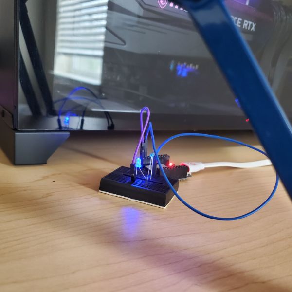
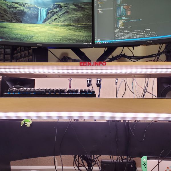
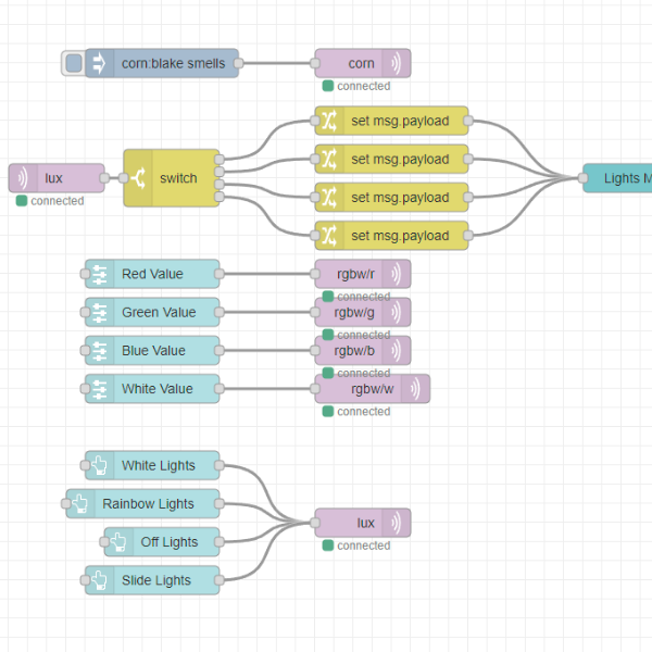
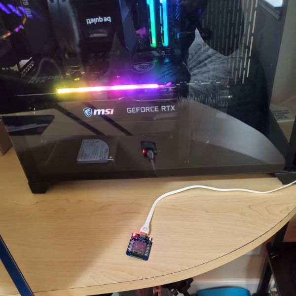
Breadnet Web UI (This controls my desk lights):
http://75.38.106.136:1880/ui
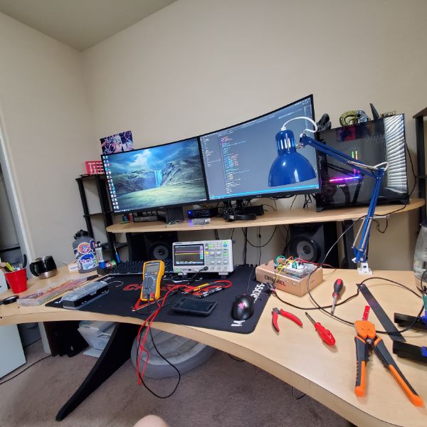
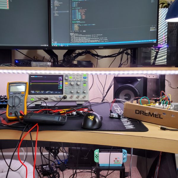
Summary: More pretty pictures. Fixed up Breadnet and got the core functionality out of it. Struggled with some data type conversions in the programming for the way the ESP32 handles MQTT payloads. Spent a lot of time tweaking things in VSCode until it worked exactly the way I wanted it. The code is super duct-taped together right now and needs cleaning up.
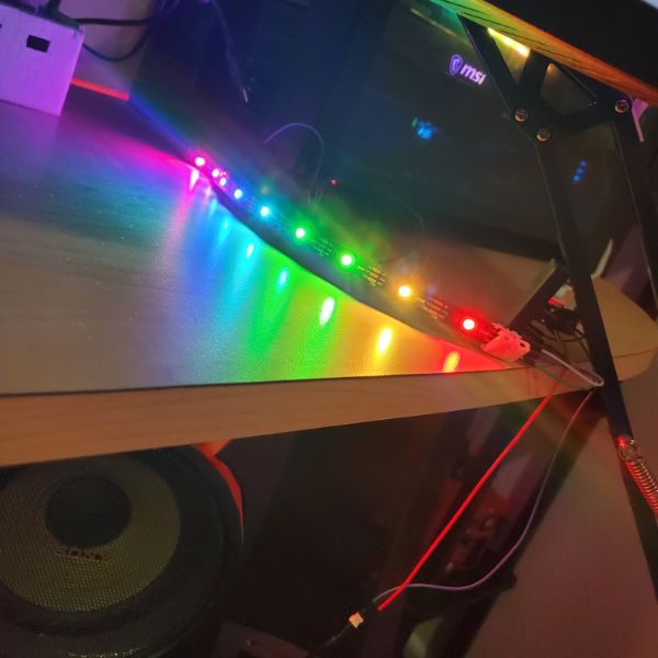
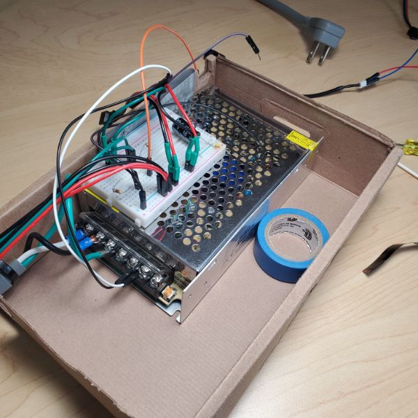
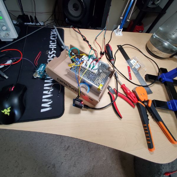
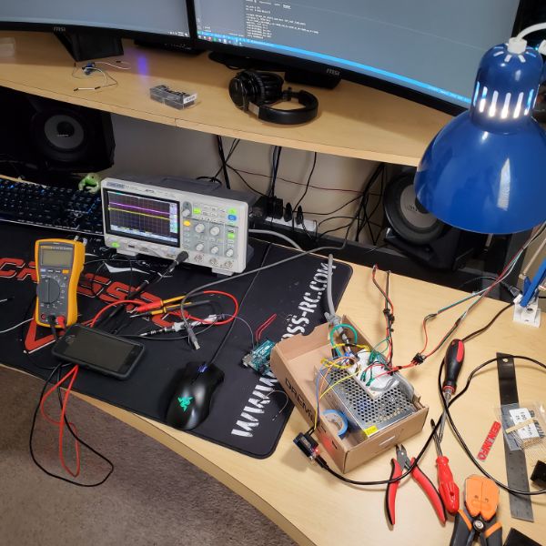
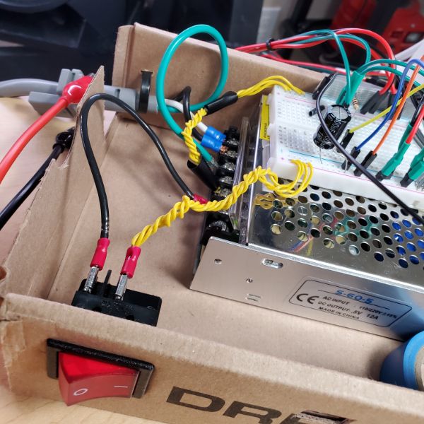
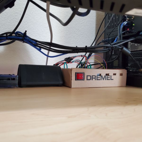
The Mega Lights controller box also had a huge fire hazard that melted the breadboard because I had about 30W of power running through two jumper wires whose terminal points on the breadboard were adjacent. No wonder it melted. The wiring issue is fixed and there’s a kill switch now. The Arduino replaced with an ESP and the lights can be controlled from the web UI.
The Prusa printer works great. I tried tuning it but any attempt I made to calibrate it further just made it perform worse. After printing some full bed size sheets I can tell I should do the finer um-calibration because the front left corner is too close during print and creates rough textures. Other than that it’s incredibly plug and play.
Next sprint will be for wrapping up the Synth once and for all, after I jump through some hoops of figuring out how to design and print some mechanical features. Then printing and putting together a new lightsbox down the line. I might design a PCB for the lightsbox, but I’m not sold on the idea because it works fine as is for now. Also working on some new storage options and putting together my new soldering station. Playing with the idea of doing some Unity tutorials and making a game but that’s for later on.
Github Stuff:
https://github.com/fishPointer/MFOS-Noise-Toaster
https://github.com/fishPointer/ESP32-Blink-Test
https://github.com/fishPointer/ESP32-MQTT-Connection-Test
https://github.com/fishPointer/ESP32-Neopixel-Test
Jaguar
Jaguar Mode
Sprint Objectives
List of Projects
Breadnet
Deploy Something Useful on Breadnet
ESP32 OTA Updates
Finish Foundational ESP32 Script
Harden Breadnet Security
Set up a Breadnet Domain
Set up a basic MongoDB on the Pi for Node-RED to interface with
Mega Lights 2
Arbitrary control of 1 LED on ESP32
Equivalent Light Strip Script on ESP32
Design Lightsbox around ESP32 prototype+Color Text
Hack into my lightbulbs and control them with Node-RED
Gridfinity
Figure out where I could put them and what I would put
Can print a max of 4×5 no larger
Twizzles
Sharpie Holder
Soldering Station
Design new Soldering Station
Importing and Editing STL Files in FreeCAD
https://youtu.be/dr1qtaURrvI
Summary
Part Workbench
Import STL
Convert Mesh to Object
Refine Object
Convert Object to Solid
Switch to Part Design Workbench
Create Body
Add Solid to Body
Proceed with Edits
Steps
1
Create a new FreeCAD Document
2
File > Import > .STL file
3
FreeCAD imports the STL file as a Mesh. Convert the Mesh to an Object that can be worked on by switching to the Part workbench, selecting the mesh, and running Part > Create Shape from Mesh. After running this, delete the original mesh
When this happens, it has to “sew” together many polygons at a specific tolerance to form the object. The highest precision allowed is 0.01 mm
This creates a high poly render of the mesh as an editable object
4
In order to get rid of redundant polygons, select the new Object model and run Part > Create a Copy > Refine Shape. This will simplify the surface dramatically. After running this, delete the original object
5
Now that the object has been refined, all that’s left is to run Part > Convert to Solid. This will create a copy of the object that can function as a solid. Delete the original, Non-Solid
6
Switch back to Part Design workbench, then create an empty Body in the project, and add the newly converted solid to that body as a Base Feature. From there, you can sketch, add pockets and extrusions, etc. And should be fully functional for edits
FreeCAD Wiki – Draft Shapestring Tutorial
https://youtu.be/_D5WJqd1SSE
I’m getting frustrated over text every time I try to use it
Back to CAD tutorials and taking my time to make sure I understand what’s actually happening
First, go into Edit > Preferences > Draft and turn off that god awful grid that won’t go away ever if you have show grid on when you open Draft for the first time
Second, create a primitive cube or something and go to Draft
Third, ensure the correct work Plane is selected
That’s the thingy that says “Top” and lets you pick the XY, YZ, XZ plane
Once the String is created, switch back to Part workbench and Extrude the ShapeString as is into a new solid
Make sure “Create Solid” is checked so it creates a unique solid
Switch back to the primitive, and go to Sketch workbench and create a sketch on one of the faces
Create an anchoring line and then switch back to the extruded text
Open the position properties and start incrementally adjusting it until it’s in place
After angling it to the correct Axis, switch back to Draft and get ready to snap endpoint move
Turn on the snapping mode, in this case endpoint snap
Then Select the extruded text body you plan on moving, and click the Move Command
From there, pick a point on the extruded text wireframe, and then select the point to snap to. In this case, the line created in the Sketch
Once snapped into place, you can verify that the extruded text solid is ready to be boolean cut from the primitive
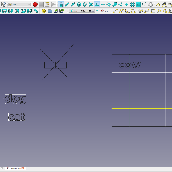
Centering Text Tutorial
I have to write it myself
Switch to WireFrame or AS-IS view as necessary
1. Create a primitive
Make a cube or something in PART
2. Create grid for text anchor points
Go into SKETCH and make a sketch
Create intersections of lines wherever you want text to be centered and anchored
3. Convert the grid into draft lines
Switch to DRAFT and convert the sketch into draft lines
Select all of the newly created draft lines and UPGRADE them
Create a linked group of these upgraded draft lines for tidyness
Hide the sketch. If the lines were upgraded properly, they should be white instead of black
4. Create the text
Use the shapestring to create some text off to the side
Immediately switch to SKETCH and open a sketch on the plane the text is on
Reference external geometry to get the four outermost points of the string
Create a rectangle around the string and anchor the external points onto the rectangle to fully define it
Draw a single diagonal across the new boundary box
5. Anchor the text
Switch to DRAFT again and set snaps
Turn on SNAPPING and turn on MIDPOINT SNAP and INTERSECTION SNAP
Make sure the boundary box Sketch is visible
Select the ShapeString for the text and click Draft>Move
Select the midpoint of the diagonal via midpoint snap
Select the intersection point of the upgraded draft grid lines via intersection snap
6. Repeat for all Text
7a. Extrude Text
1/2
Go into PART and Extrude the ShapeStrings
Select the base feature of the body (the cube) and the extruded string
Boolean Cut
7b. Pocket Operation Text
2/2
Go into DRAFT and convert one or all of the positioned ShapeStrings into Sketches
Go into Part Design, select the Sketch(es) and Pocket/Pad operation
Desk Accessories
Design a Cable Holding Clip for Megadesk Midpiece
Phone Holder Slide Clamp
Megadesk Center Cover Card
Upper desk is 20mm thick
Shopping
Buy a Second Trash Can
Buy more Jumpers
Buy some helping hands that don’t SUCK
Look into keyboarding tools
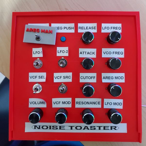
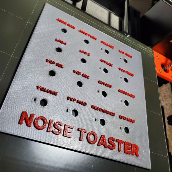
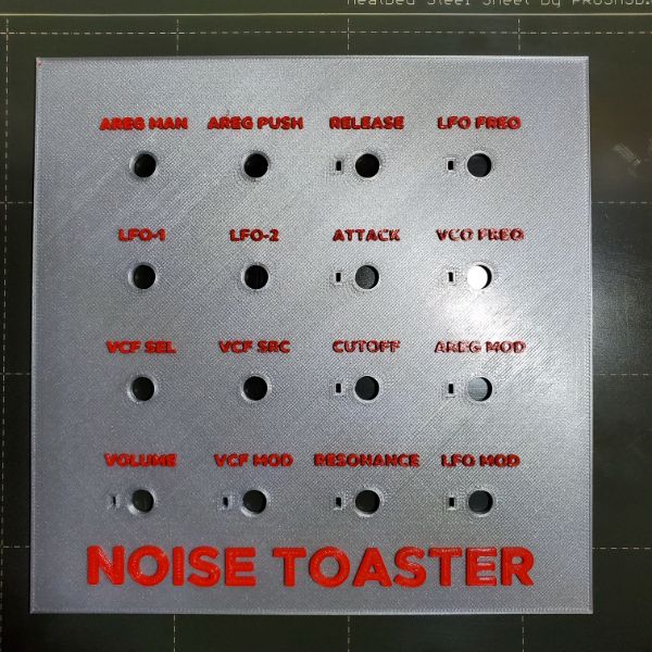
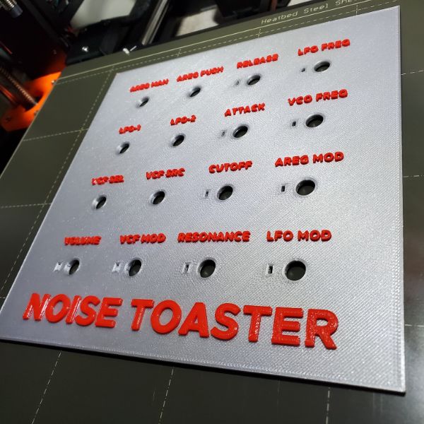
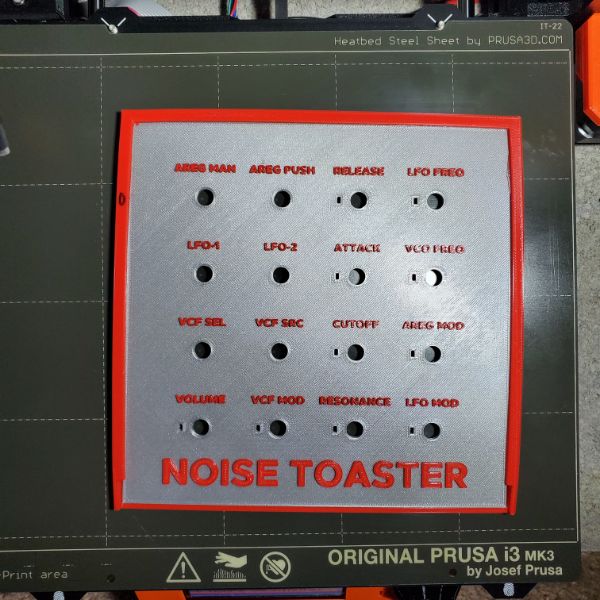
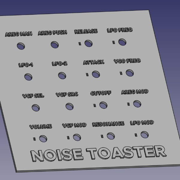
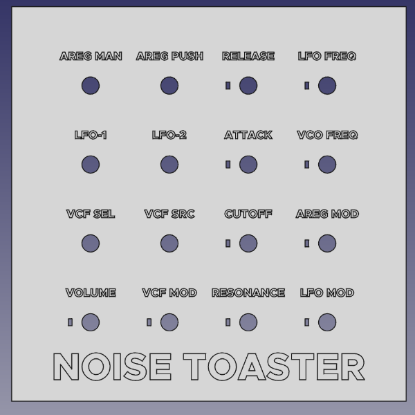
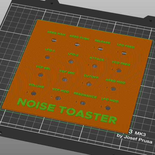
Noise Toaster
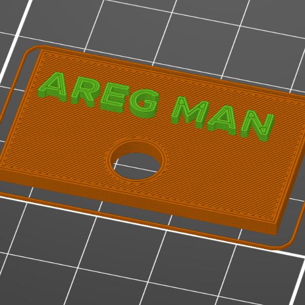
Multicolor Embedded Lettering in FreeCAD->PrusaSlicer
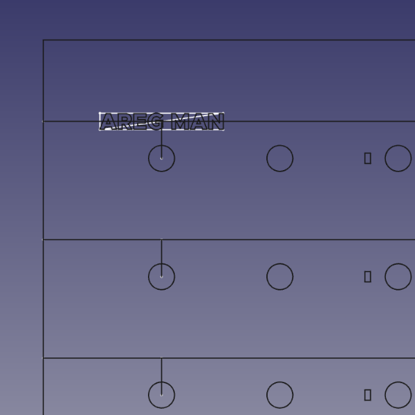
Redesign Synth Case
Timelapse Video – Soldering together second Synth
Mobile Power Supply
Mobile Power Supply Tutorial Series
Skilling
Unity Tutorials
Map C++ Resources
AoE Chapter 2
Monty Choy Interview Questions
Gridfinity
Links
*DOWNLOAD THE MODELS!*
📥 Divider Bins + Trays: https://bit.ly/3E6vNrR
👁 Window Bins: https://bit.ly/3OaI2YP
🍽 Baseplates: https://bit.ly/3781R2A
🖨 Printer-Mount Baseplates: https://bit.ly/38FOJ4R
🖨 3D Printer Accessories: https://bit.ly/3jtTfWu
📏 Caliper Holder: https://bit.ly/3EpMlv3
🔧 Ratchet + Socket Holders: https://bit.ly/3vcZ5B0
🔩 iFixit + ES121 Driver Holders: https://bit.ly/3xnsCdL
🛠 CNC Tool Holders: https://bit.ly/3KFjRj1
⚙ CNC Collet Holders: https://bit.ly/3JvubsE
⛏ Pick + Tweezer + Scraper Racks: https://bit.ly/3uD827I
🖊 Pen + Pencil Holders: https://bit.ly/3vaUCik
✂ Nippers + Strippers + Scissors Holders: https://bit.ly/3JFnRiu
Notes
Printing a 4×4 baseplate grid to start
With some little squares it fits great
I just, don’t know where I should put this or how big I should go…
NT – Noise Toaster
BN – Breadnet
Setting up on new router
Had to change all the 10.0.0.x back to 192.168.0.x
router pass g
After struggling to port forward anything, even a simple minecraft server, I looked up a list of common port forwarding issues, and one listed was that a lot of people don’t even realize they’re actually behind multiple routers. And so I installed a router counter and it turns out I am in fact behind two routers, the second one is mine, and the first is the AT&T thing in the garage
http://www.pcwintech.com/shanes-toolbox
My Router
192.168.0.1
ATT Router
192.168.1.254
Okay so
DLINK Router (mine)
Simple Port Forward
Just add a custom service to your IP
Device IP
ATT
Use Device Access Code found on back of router
Firewall
NAT/GAMING
Manage Custom Services
Create a Custom Service with the port you’re trying to open
Add the Custom Service you just made, and select the Device it’ll apply to
In this case, the device is the second router
192.168.1.65/unknownecade02eff78
Rinse and repeat for each port you’re opening
VSCode uploading to wrong port
You can specify which port you upload to
[env:uno]
platform = atmelavr
framework = arduino
; any port that starts with /dev/ttyUSB
upload_port = /dev/ttyUSB*
; COM1 or COM3
upload_port = COM[13]
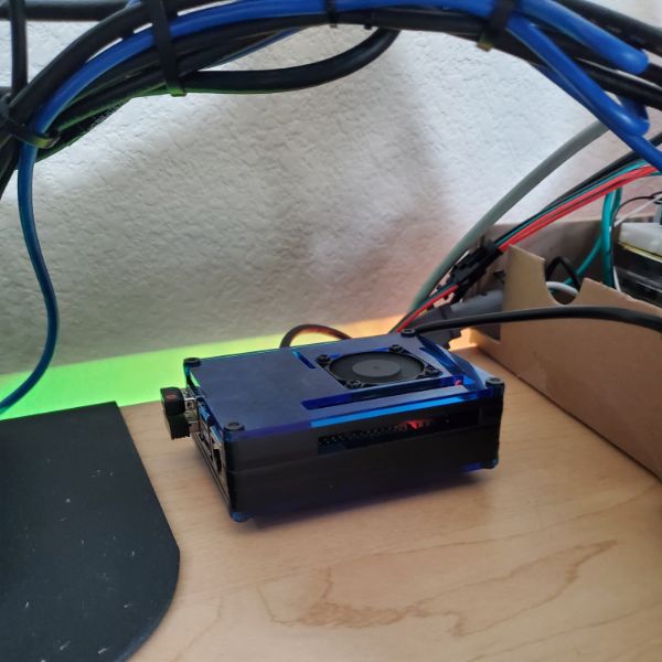
Bare Minimum Breadnet Achieved
Raspberry Pi running Node-RED and MQTT
Port Forwarded
1880 for Node-RED
1616 for MQTT
ESP32 MQTT Connection Test
Setting up a fundamental script, making sure it’s clean, documented, capable, and commented so I can return to it in the future.
Not sure how to structure these notes for now but
in void reconnect(), make sure all topic subscriptions are in this
The first time the MQTT network is connected to is in the reconnect function which is called in loop, so technically there’s no setup for it
in void setupMQTT()
the setCallback function only gets called once and assigned once per mqtt instance, so I think everything has to be inside the singular callback function
So really, theres only three important functions in the program
void setup
void loop
void callback
Speed Test
I ran an unconditional publish script to post “AAA” every loop and it posts very quickly. It can do about 10 posts/millisecond
so 10,000 posts a second? jesus
Topic Char* issues
referencing the char* that is the “topic” variable in the callback can’t be referenced to use the topic itself as a string for a future messages payload
meaning, I’m trying to make the payload for a response message to be the topic of the initial message, and it’s not working
Node-RED Booleans
Node-RED boolean switch outputs yield a string of ‘true’ or ‘false’
so instead, make the payload numbers of 0 or 1
MQTT Outputs
Binary-Ascii Characters Table
https://www.binaryhexconverter.com/binary-ascii-characters-table
The payload comes in the form of a byte
If you cast that byte as a string and print it to the serial, you’ll get the ascii code for that binary
example
payload: 0
instead of getting a string for ‘0’
you get a string in binary that represents the character zero
I can’t figure out how to get a number
MQTT passes ASCII data
so even number 0 results in 48
I can print back on ESP32 in Serial the payload byte and get 48
I can print back the char(payload) byte and get 0
but that’s still a char, I can’t get a numeral zero to work with
Success!
byte -> char(byte)
String(char(byte[n]))
int num = String.toInt()
Code
case 3:
Serial.println(payload[0]);
Serial.println(char(payload[0]));
//String popcorn;
popcorn = String(char(payload[0]));
Serial.println(“popcorn”);
Serial.println(popcorn);
shrimp = popcorn.toInt();
Serial.println(“shrimp”);
Serial.println(shrimp*5);
if(shrimp*5 > 12)
{
Serial.println(“you did it!”);
}
Waiting to upload to github until I clean it up more and demo it a bit, but wanted to write it down
It seems like I also need to convert the post-calc integer back into a char format in order to publish the results
Finally
server delivers a BYTE*
ESP32 takes BYTE* and converts it into a CHAR
then stores that CHAR into a String object
then String.toInt() to get an INT
then do math on that INT
then itoa() that INT into a CHAR
then publish that CHAR back to the server
Flag Colors
Red
176
5
5
Black
24
24
24
Grey
69
79
71
Green
0
242
98
ML2 – Mega Lights 2
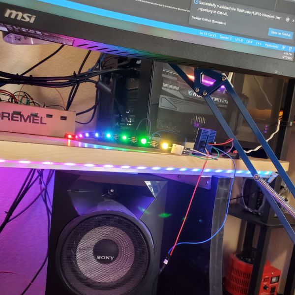
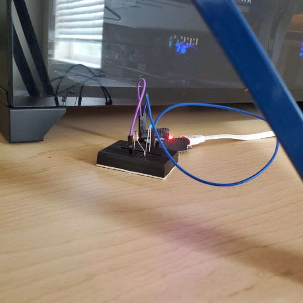
ESP32 Neopixels
ESP32 works perfectly fine with copy/pasted code from the Arduino sketch for Neopixel control, which is good news
Unfortunately, the ESP32 can’t take 5V input. I think the max is 3.6 – 3.9V, so I need to find a way to lower the input voltage of the 5V supply.
I’m guessing that a level shifter is for control signals and not really for power transmission, so the best solution is probably to just use the other buck converter from the pack of two I bought for the old 3D printer
As I expected, the rainbow pattern is working, but it’s choppy and slow with mqtt running
I disabled MQTT’s client loop and just ran the pattern and it was nice and smooth again.
Having i print millis() after each light update cycle, it looks like they’re about
163 ms Light Cycle without MQTT
164 ms Light Cycle with MQTT
73 ms Light Cycle on Arduino
I think I might’ve just had the hue shift value at 32 still…. and that’s why it was choppy
ohh
I took .show() out of the loop so it doesn’t show after each pixel.
It seems like show is the longest part of the function, it’s so much smoother afterwards
I don’t remember messing that up, but now with show outside its
3 ms Light Cycle with MQTT
Verify ESP32 working with Buck Converter
I can’t tell if I should be plugging into VCC or 3.3 on this board’s pinout
I bought it on Aliexpress so its pinout doesn’t match anything else and I can’t really follow the traces visually
I’ve got plenty to spare though!
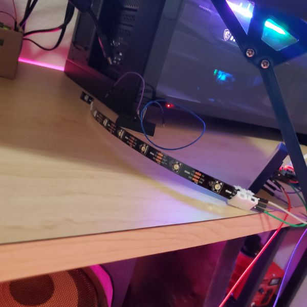
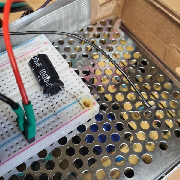
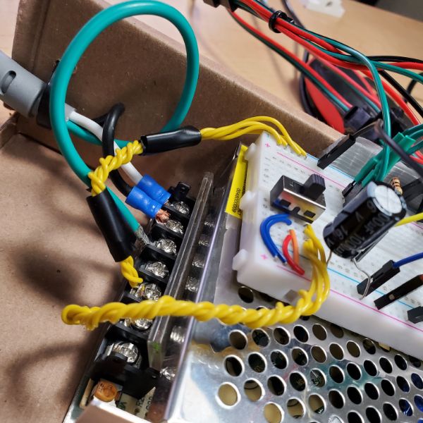
Melted Wires
There’s some intrinsic heat generated in the jumpers. They’re not meant to carry 2.5A.
Well, it kind of seems like they can handle it, but they used the breadboard as a heat sink
That, in combination with the breadboard being ON TOP of the power supply, and the voltage and ground wires being side by side, combined to make a very slow breadboard melting device.
Running it with just one or two branches of lights results in a tangible warmth coming from the wires. So, I need to do something about that
The best idea I can come up with as a temp fix right now is to just make sure the power and ground rails are on opposite sides of the breadboard, and then run multiple jumpers for each to diffuse the current.
And then tap them in at different points along the power rails, of course
Notes
i have all of the power running through a single jumper wire
and it melted the breadboard
so i need 2 wires
about 30W of energy if all lights are on, but it gets warm and compliant with just 1/4th of them
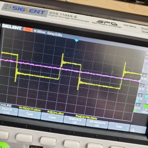
The lights flicker every now and then, not sure why
I can also distort the signal by putting hands on the wires
I’m guessing this whole thing just needs to be wired a little more securely
Lightsbox R-1
Took out the buck converter
It turns out that the ESP32 takes in about 5V from the USB when programming it, so why shouldn’t it be able to take 5V from a power supply?
I found that using the buck converter and inputting 3.3V actually interfered with signal integrity
I also figured out that the current limiting resistor of 400-600R is too high for the ESP
If you try to connect all 4 strips to a single PWM pin, the current draw is too much and the signal collapses. I had to reduce the R all the way to 100 for the signals to not crash
To in summary, increased input voltage to 5V (4.95) and decreased output resistance to 100R
I also found that braiding 4 solid core jumpers together solved most of the overheating problem. I still wanted a switch, so I inserted a breadboard switch, but it quickly became too hot to touch with all the current running through it, so I replaced it with one of the chunky breadbox switches I Had leftover. I had to crimp some terminals to get it installed but it was worthwhile and now nothing seems to overheat
I melt-tested by turning all the lights up to 255,255,255,255, which draws an insane amount of current.
The hottest thing in the box is actually the power supply at that point.
The connection between the crimped terminal and the breadbox switch that runs to the breadboard seems a little shoddy. I kept touching it to see how warm the braided cables are but it caused the lights to flicker off momentarily. If I do it too much and it turns off for too long the ESP also powers down.
For now, the lightsbox seems safe enough and I should be clear to move onto other things while enjoying the first practical application of breadnet and the fancy lights I put so much time into
I noticed a stuttering issue that I thought was due to the resistor being too high still, but it was regular. I correctly guessed that sometime during the mqtt check loop it defaults to light status = 0 and clears the pixels. I turned that if/else into an if/if. So technically there’s no default command for the lights anymore, which got rid of the stutter
Lightbox R0
AC Power Port
https://www.amazon.com/button-Adapter-Connector-Socket-MXRS/dp/B082ZFRV1B/ref=pd_day0fbt_img_sccl_1/144-7350682-5806604?pd_rd_w=7X3VD&pf_rd_p=bcb8482a-3db5-4b0b-9f15-b86e24acdb00&pf_rd_r=SX1JSAA9SA8365BYANJM&pd_rd_r=2a07e6ad-f631-4baa-9e80-f91427ab0b17&pd_rd_wg=Swye7&pd_rd_i=B082ZFRV1B&psc=1
Comes with a switch! $8
PCB
Could design a PCB that has a buck converter, the necessary circuits, and the EPS32 in it all in one
The weakest part of the circuit right now is the fact that all the power coming from the power supply is carried to the breadboard by a single jumper
So the best way to fix that is to get thicker wires, or more wires
If i had a PCB, I could make some large heat dissapation zones and then have similar screw down terminal clamps
I could probably do that with a proto board
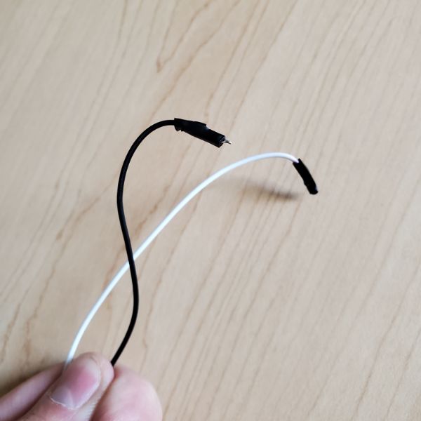
Cables
Thicker cables are needed
Maybe 16AWG to be safe?
https://www.amazon.com/dp/B079CFZZYS/ref=sspa_dk_detail_5?psc=1&pd_rd_i=B079CFZZYS&pd_rd_w=yyeqR&pf_rd_p=0c758152-61cd-452f-97a6-17f070f654b8&pd_rd_wg=esIgs&pf_rd_r=0Z2ETXA7DD813T1W40HE&pd_rd_r=c0528a0e-5856-4ea6-b460-eca03ea59510&s=electronics&spLa=ZW5jcnlwdGVkUXVhbGlmaWVyPUEyUEJPMVRRWkFBQU1QJmVuY3J5cHRlZElkPUEwODg0OTQyM01RREdGUVoyQlhWSSZlbmNyeXB0ZWRBZElkPUEwOTg0NzgwM1ZTSjlNV0xNVERNTyZ3aWRnZXROYW1lPXNwX2RldGFpbCZhY3Rpb249Y2xpY2tSZWRpcmVjdCZkb05vdExvZ0NsaWNrPXRydWU=
Also need some terminal blocks to clamp down in that case
The power rails only go to the strip and the ESP32 anyway!
More specifically the buck converter
C++
https://www.cplusplus.com/
https://isocpp.org/
Unity
AoE
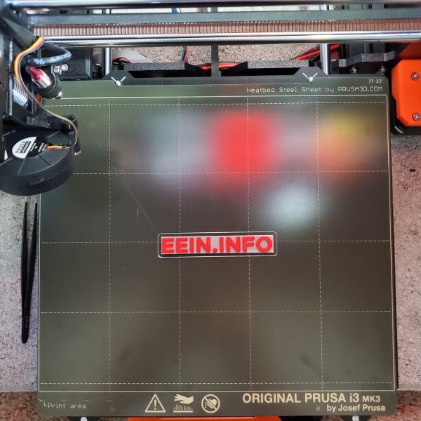
Prusa Tuning
Going through the teachingtech calibration guide, but maybe this time it’ll stick hahahhahahahaha
Running GCode over USB to the printer to minimize crouch time
It actually looks like the printer gets worse the more I tune it. more prusa magic?
PID Tuning
The Prusa has a built in PID Tuning button, so ez
First Layer Tuning
Starting with all the default settings
Bed Dimensions 210 x 210
Temps 210/60
Printer is Direct Drive so
1mm Retraction
60mm/s print speed
Z-Axis Calibration
Started at -1.225
Distinct Ridges
-1.000
Distinct Gaps
-1.125
Seems to work great!
Confirmed, -1.125 is just about perfect, according to the results I’m seeing on the test pattern
Correction, Print Dimensions are
X: 250
Y: 210
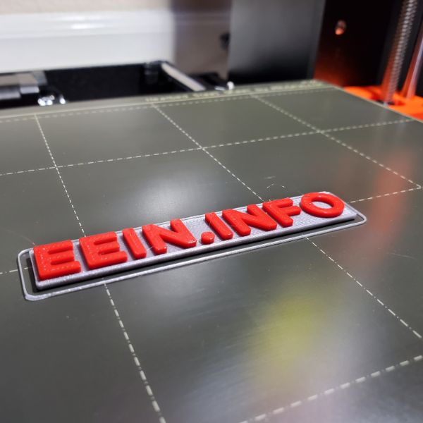
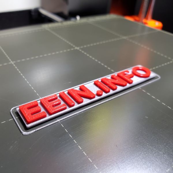
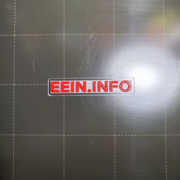
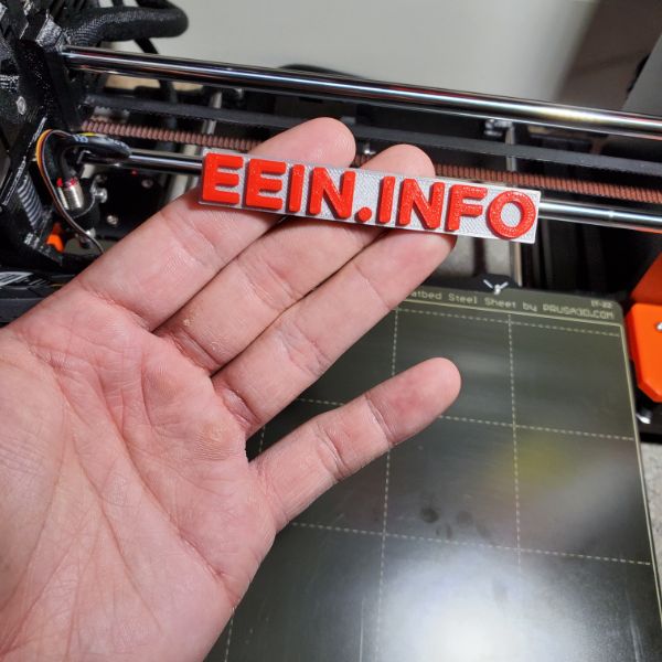
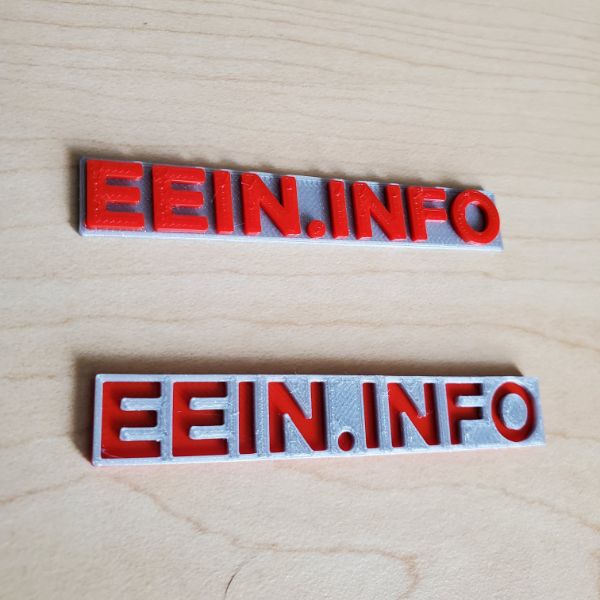
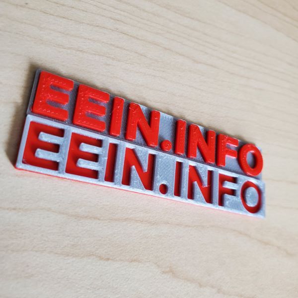
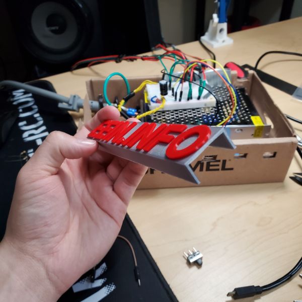
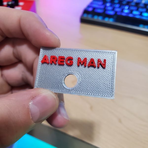
Text Embossing
FreeCAD
Go into Draft mode
Create the text string
Select the font file
Select the anchor point (bottom left)
Then click the button on the top bar to convert the SuperString into a Sketch
Apply that Sketch to a Body
Pad it onto ANOTHER PRE-EXISTING BODY so you don’t get a “multiple solids” error
Enjoy
For reversing the text, make sure the pad direction is inversed, and then pocket the text
Color Changing
It’s actually super easy to add a color change prompt
Just Slice the STL, and then navigate to the first layer that should have the color changed, and then click the plus icon next to the layer select node on the vertical line
Project Idea
Flashfire Box
It’s a box
And there’s a metal grate floor
And there’s lighters at the bottom
Well not normal lighters, just the lighting mechanism, and they’re bigger
and they’re electronically controlled to make a brief flash of fire
burns off the stringies on 3D prints
Also cool to flash some fire
Minecraft Server
https://www.bisecthosting.com/blog/craftbukkit-vs-spigot-vs-paper/
Paper is fastest
https://www.bisecthosting.com/blog/five-essential-client-side-mods-for-minecraft/
https://apexminecrafthosting.com/top-10-minecraft-plugins/
WorldEdit
Dynmap
EssentialsX
Clearlagg
Holographic Displays
Factions
LuckPerms
mcMMO
WorldGuard
SilkSpawners
Timber
Vault