Project Summary (Technical Overview):
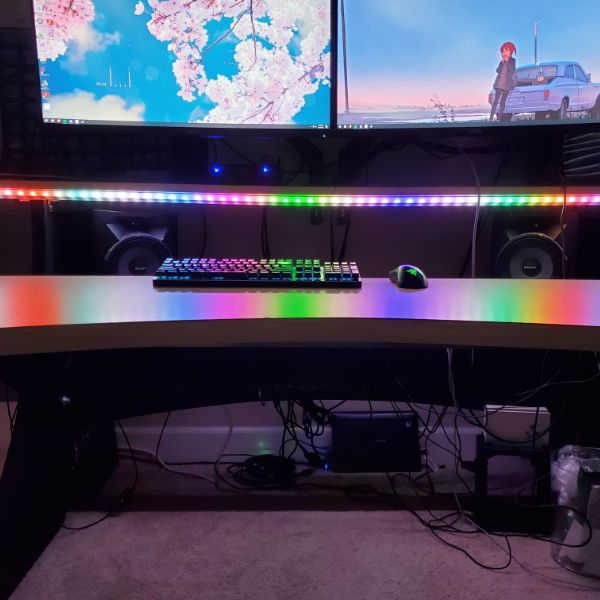
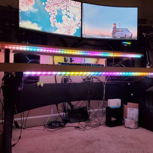
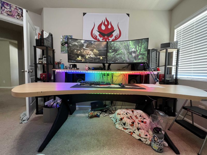
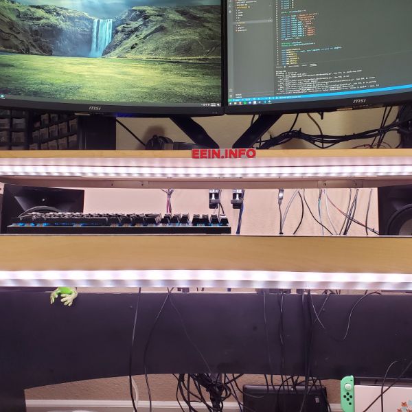
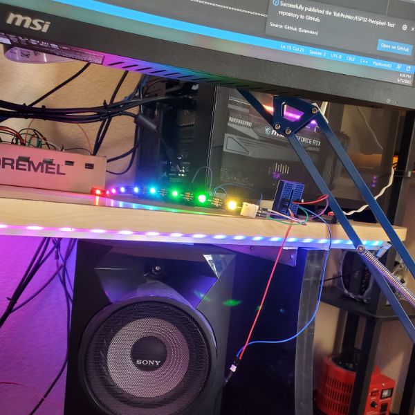
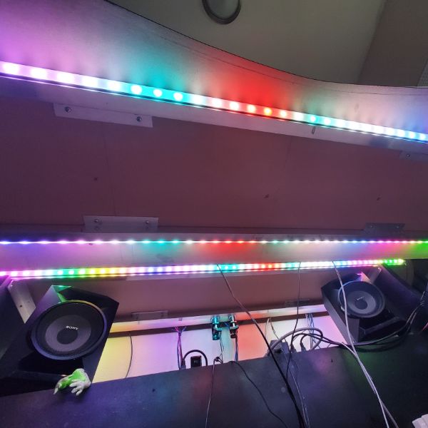
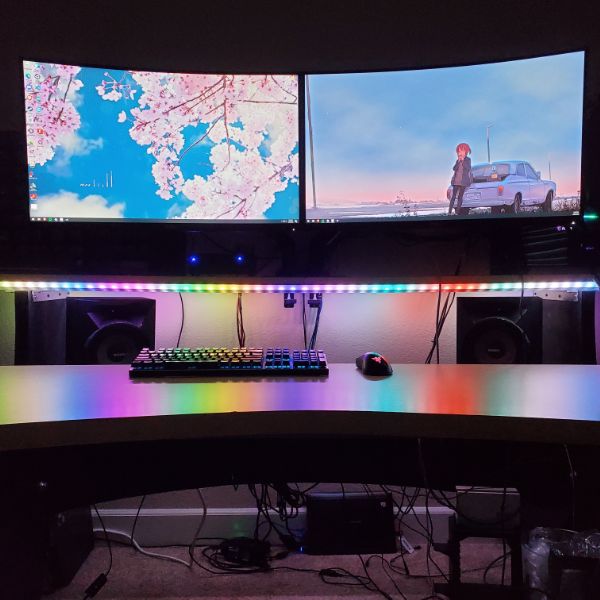
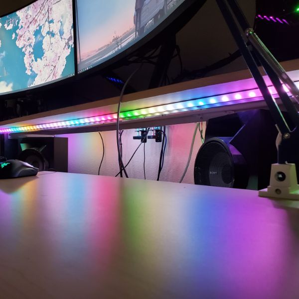
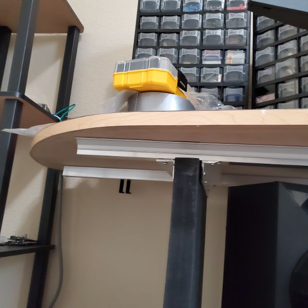
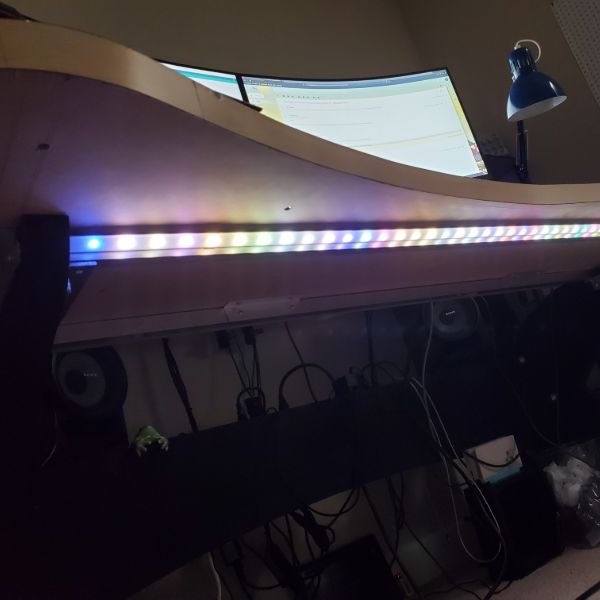
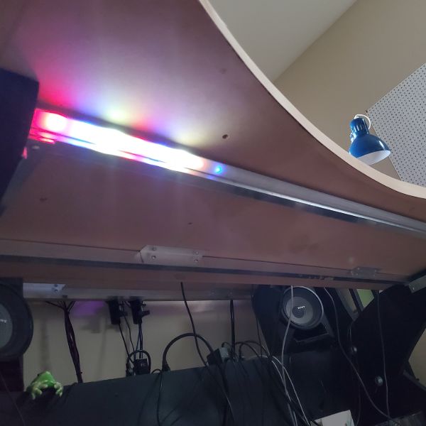
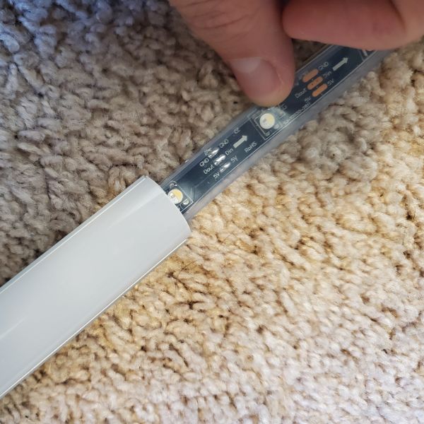
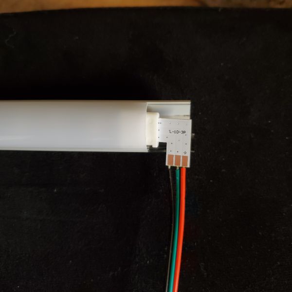
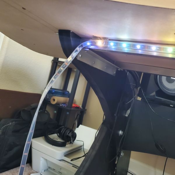
I used aluminum channels and plastic diffusers to mount LED strips to the existing aluminum rails of Megadesk and tried to make it look as professional as I could. I used SK6812 strips which are RGBW, with the additional white pixel, as well as individually addressable. I had to get 2 x 5m strips, which cost around $180. I also learned to use right angle flex-pcb connectors on LED strips so they don’t bend/get crimped, as well as these bridge connector things.
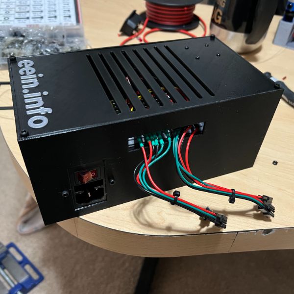
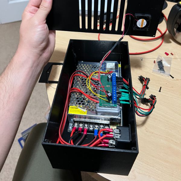
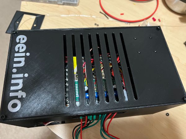
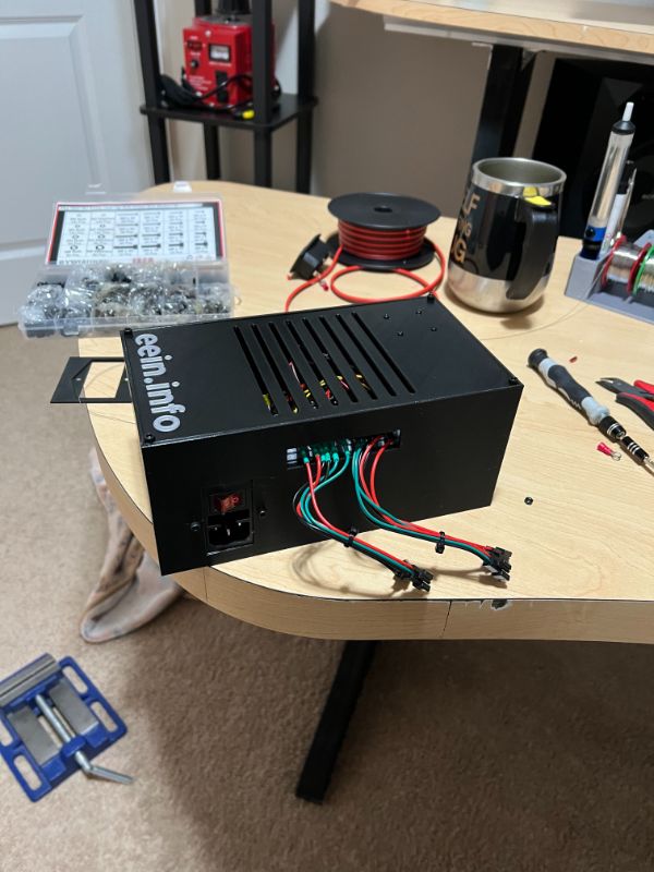
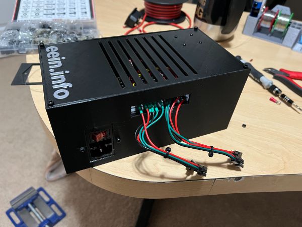
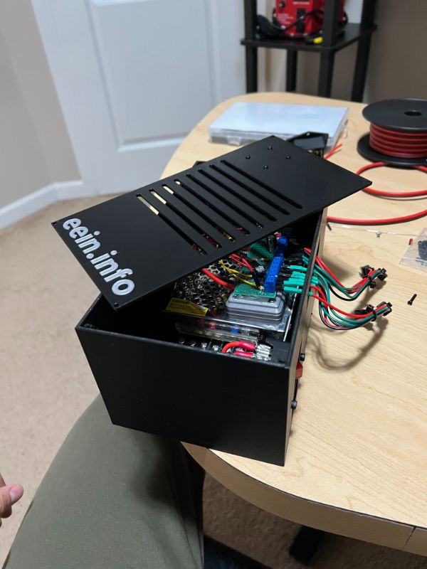
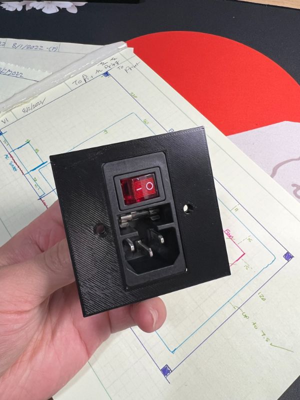
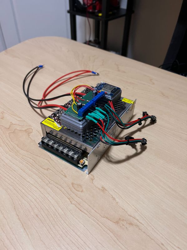
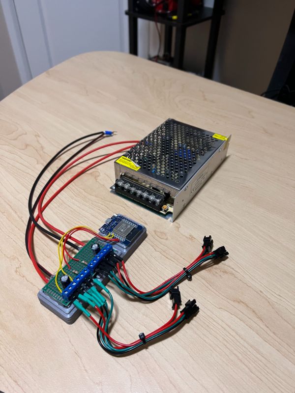
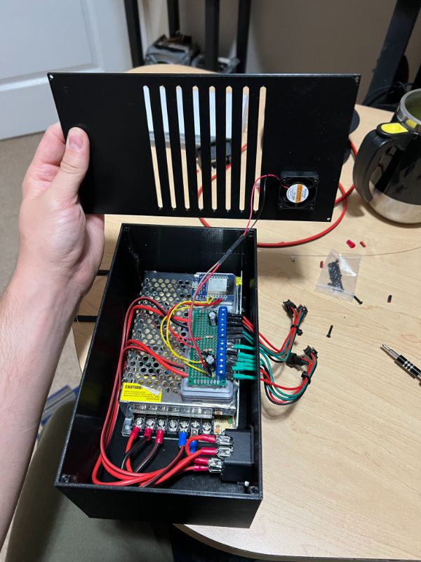
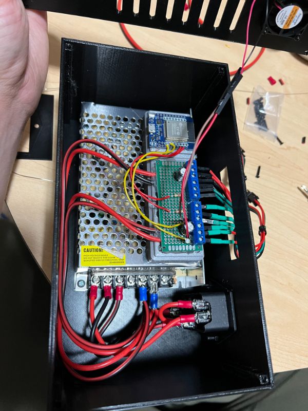
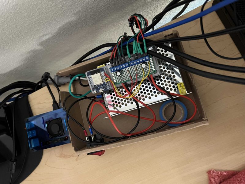
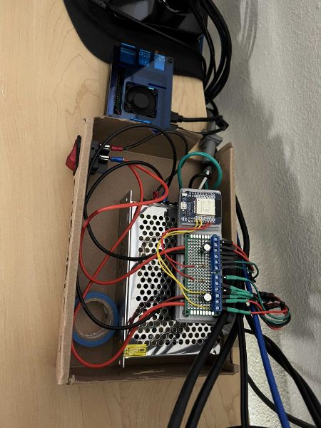
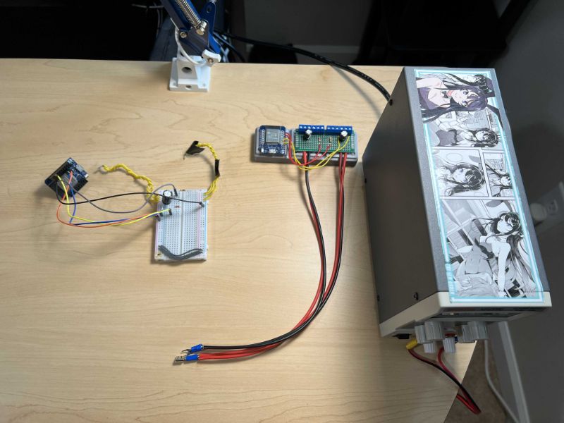
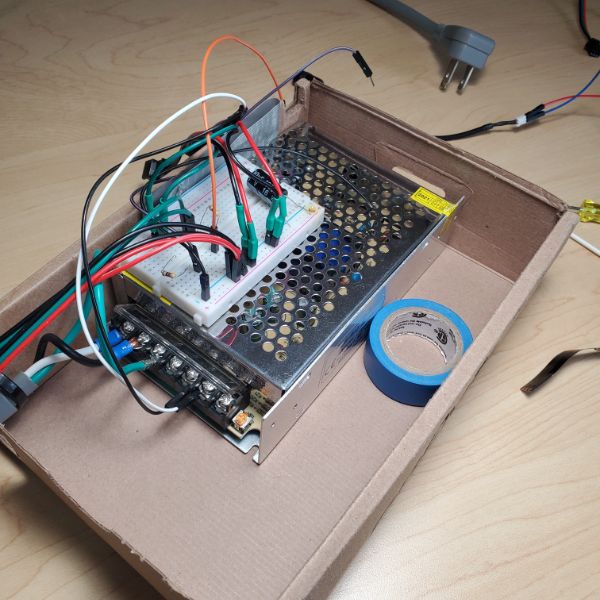
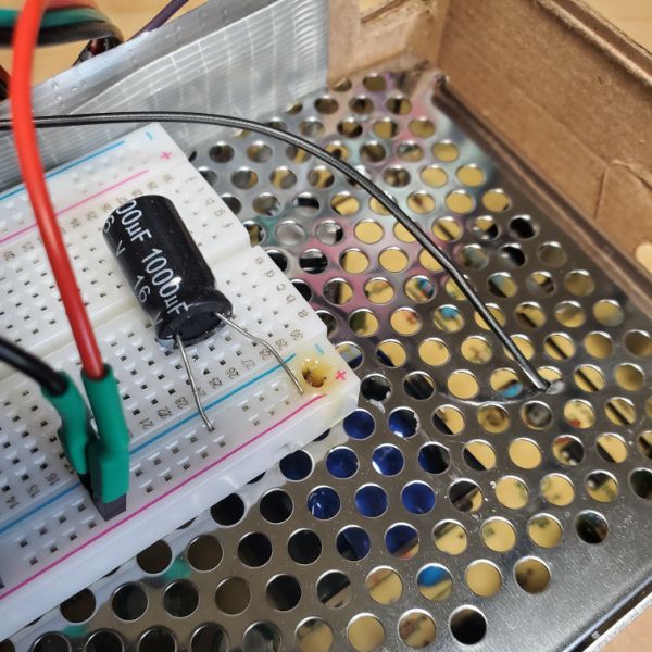
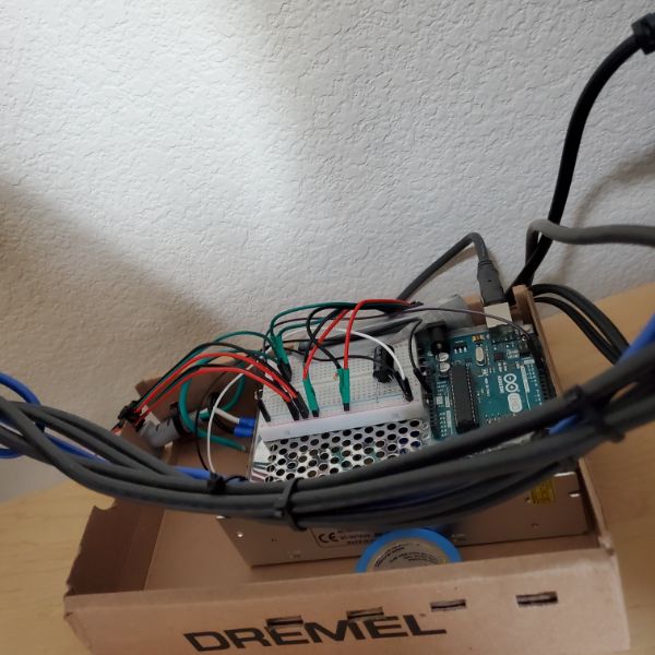
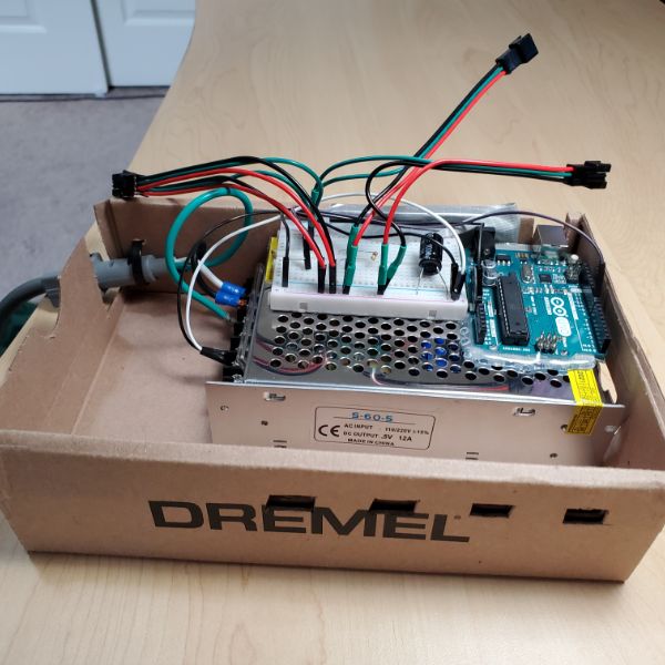
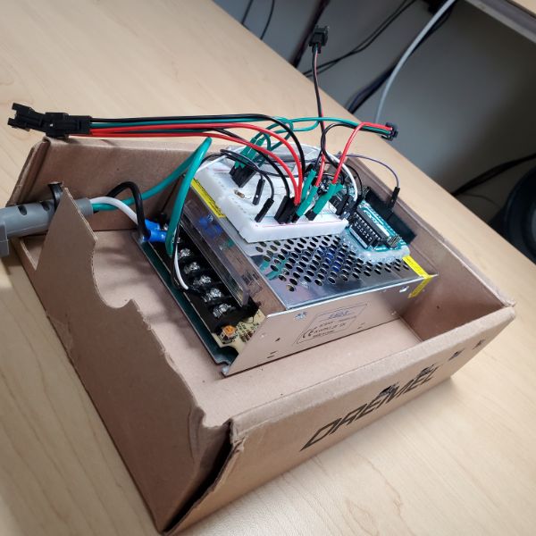
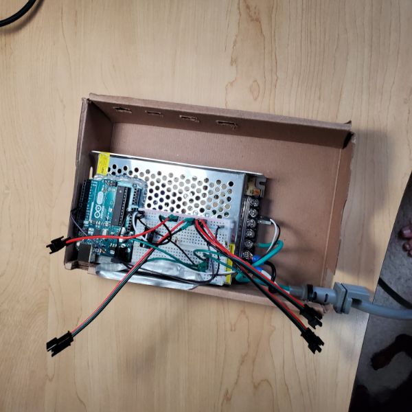
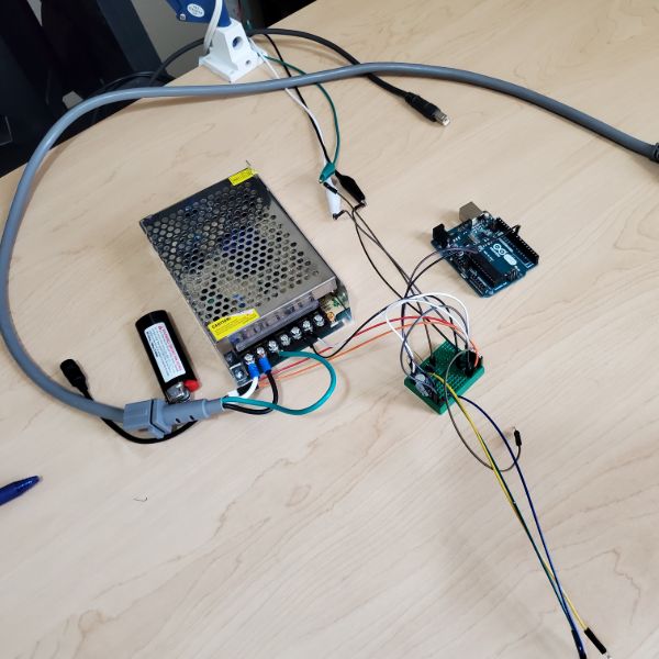
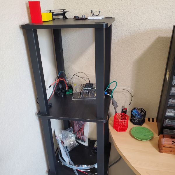
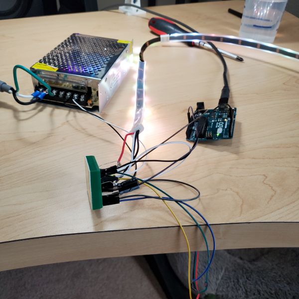
The lights are controlled by an ESP32 using the Adafruit Neopixel library, and are powered by a generic 12A 5V power supply. I designed and 3D printed an enclosure to hold the power supply, ESP32, and control board. This is the first project I’ve used a formal female AC power socket, which went very well. The control board is basically just a few current limiting resistors and some capacitors for power stability to help the ESP32.
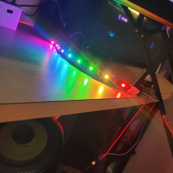
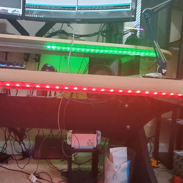
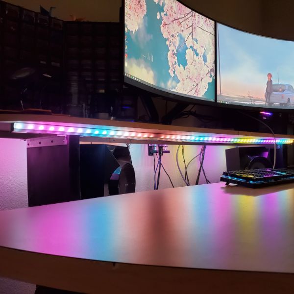
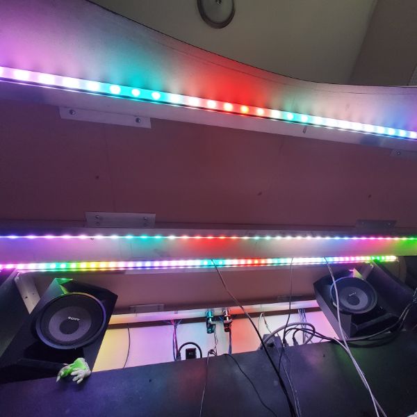
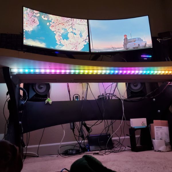
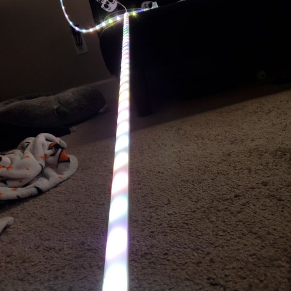
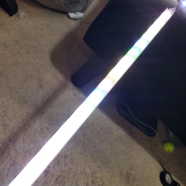
The ESP32 is sending 2 PWM signals to the upper and lower desk sections respectively, and they can be controlled independently. The lights currently have four modes: Off, White, Rainbow animation, and RGBW Slider. The lights are controlled primarily through the Breadnet Node-RED UI.
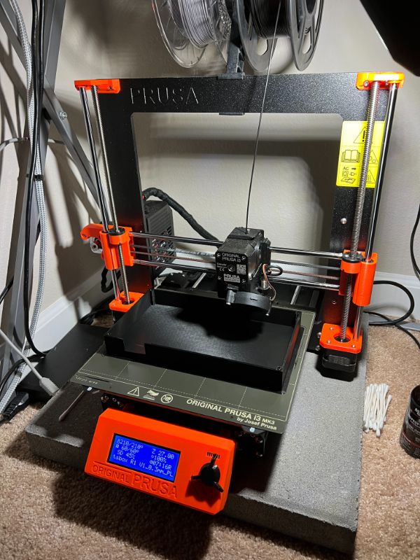
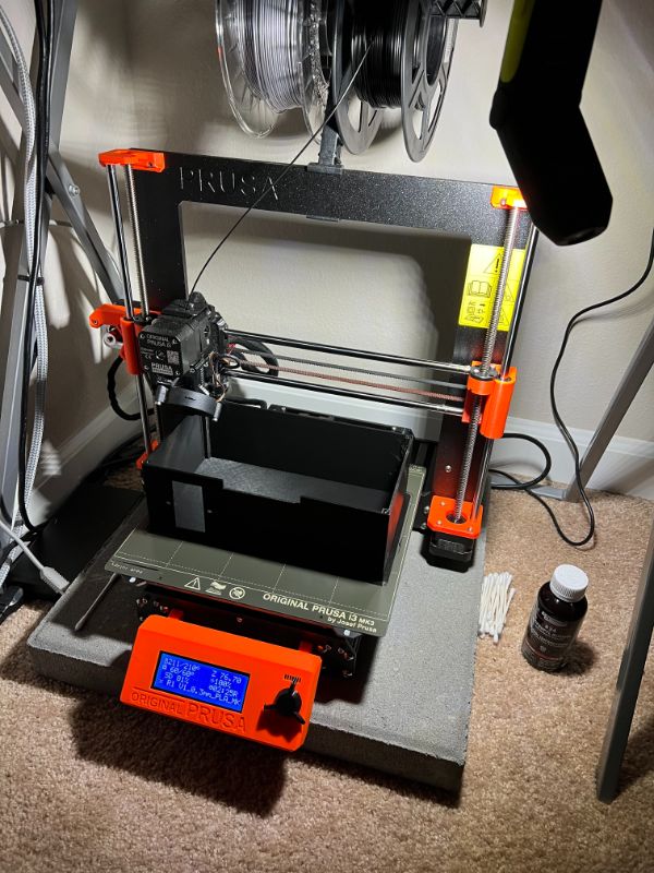
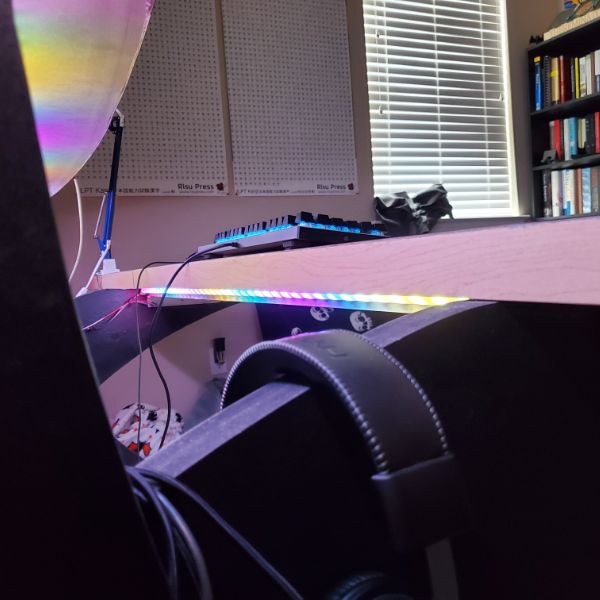
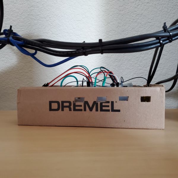
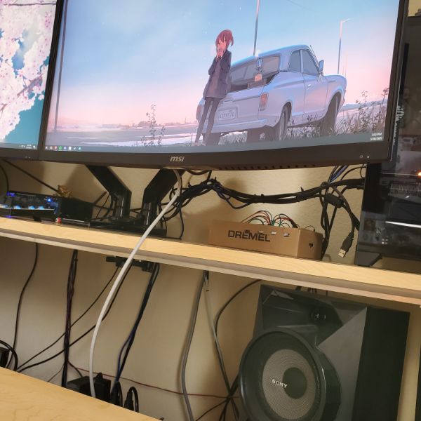
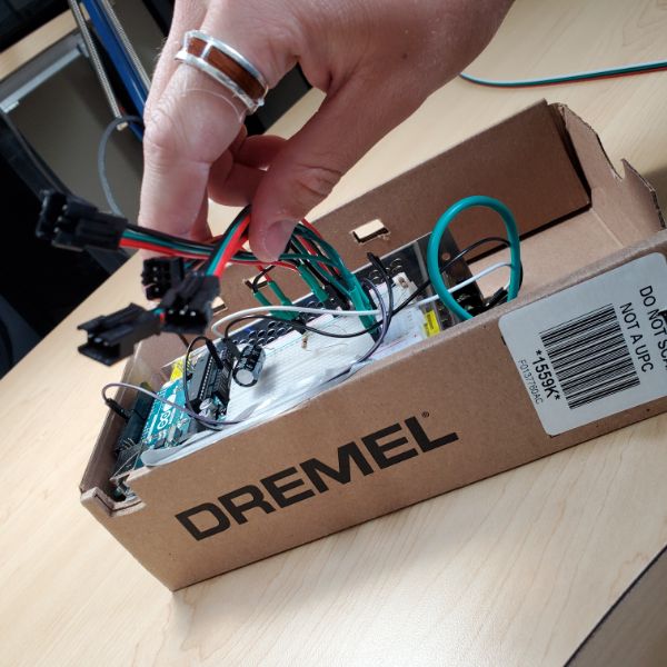
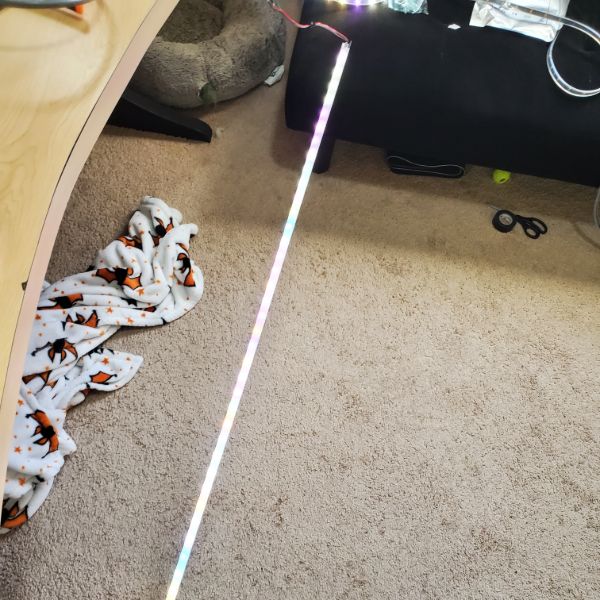
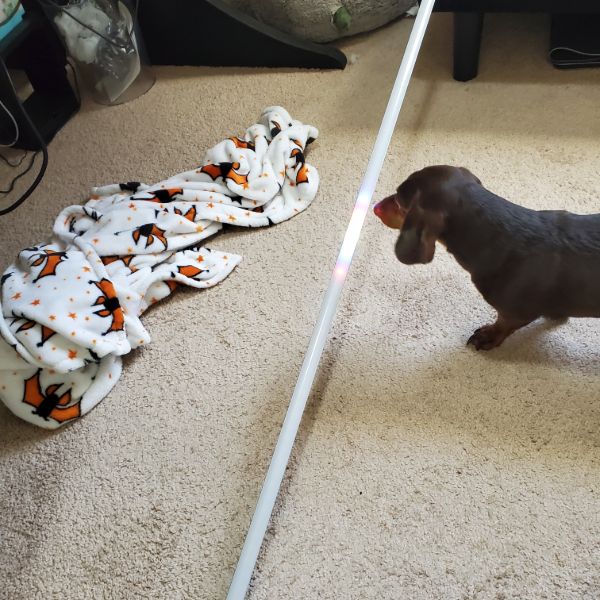
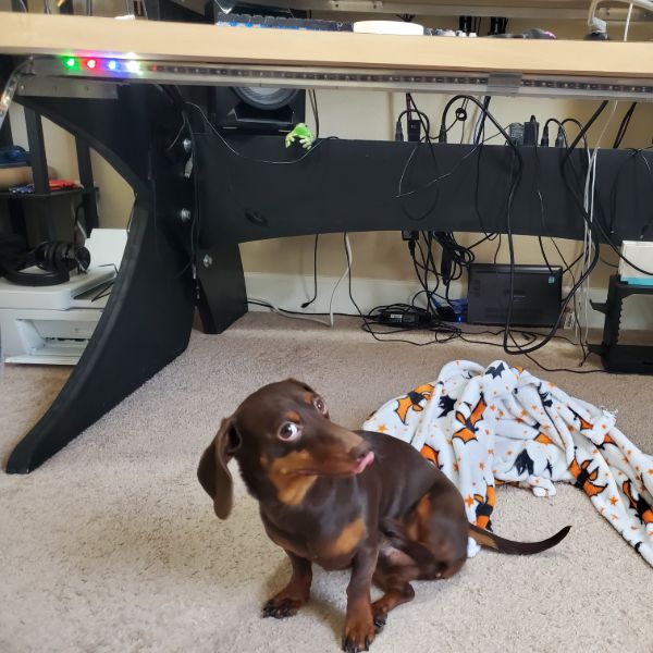
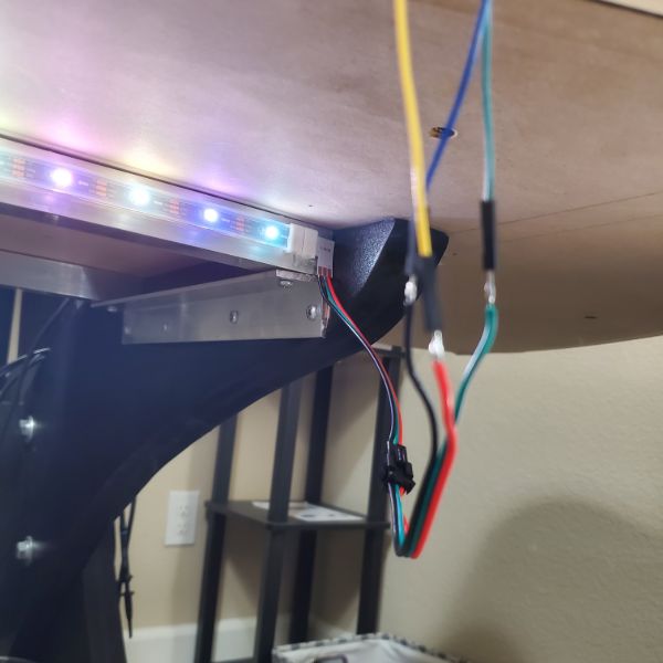
Final Project Pics
Project Summary (Personal Overview):
This project was pretty easy but took a while, and was more expensive than I was hoping. But my birthday crossed it so I just asked my mom to buy the strips. Otherwise I couldn’t really justify buying them lol.
Getting the channels installed was a pretty nerve-wracking and tedious process because I am always nervous installing things into Megadesk. I set it up in a way such that the channels are permanently fixed and the strips never need to get taken out or disassembled. They’re part of the desk now. I can still switch them out if some burn out, and there are cable connectors on both ends of the box and the lights so they can be disconnected and cable-managed arbitrarily as well.
Getting the lights to work was confusing and I basically just fumbled around in the dark with the library until I got something that made sense. After that I had to code the ESP32 to talk to Breadnet and then send data over to the ESP32, and then the strips. I had some issues with one PWM pin not being able to supply enough current to control all four strips. I lowered the resistor to 0 and they got more stable. Now there’s a small resistance since there’s 2 PWM signals sharing the load.
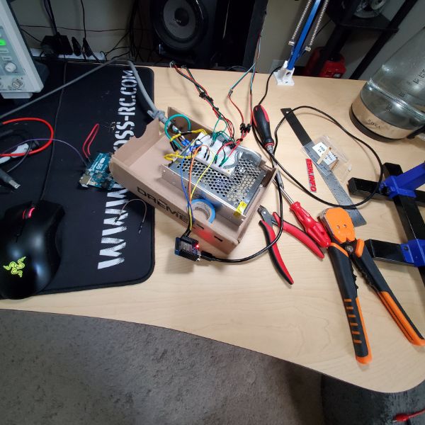
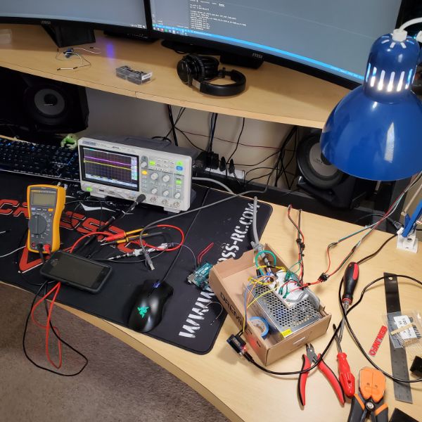
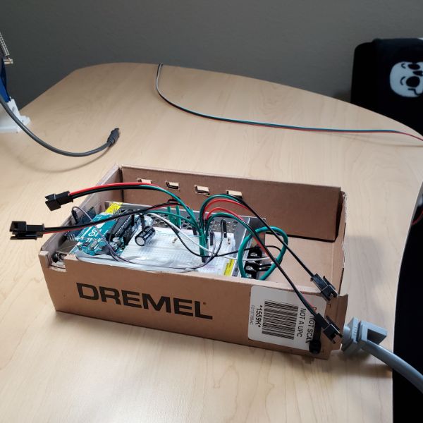
The breadboard I was prototyping on melted because I had 30W going through a single jumper wire… inside a cardboard box. Fire hazard central. The whole thing is printed and pretty polished now though, so no more fire hazard. It’s very stable and the first complete Electronics Box Project that I’ve made that has an AC socket. I like the way it came out. It didn’t cost much more than the strips and channels.
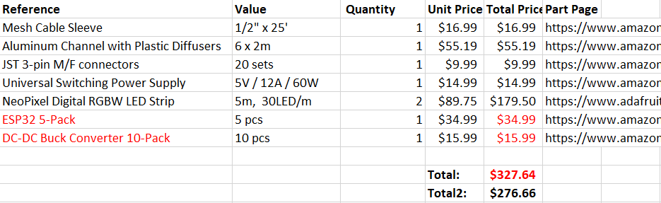
Project Cost Breakdown: $250
Project Timeline Breakdown: 4 Months
Project Gallery

Project Notes
2022-D
LED Strip Research / Breadnet Project
Lab stuff, I have been kind of avoidant and dreading diving into the power supply. I feel like I don’t have enough time to get through the whole power supply series in just 2 weeks. Along with the Synth that I added on. If the Synth gives me as much trouble in layout as it did in Spice then I’m going to have an issue.
And if the Power Supply gives me as much trouble in either Spice or Layout as the Synth did in Spice, then I’m going to have another big issue. So I’m just generally not looking forward to getting started very much, so I spent a day researching some other stuff. Printer Upgrades, Desk Upgrades, Anti-Static for my chair, etc.
BOM
Parts will cost around $300
These aluminum channels are super expensive, so it’s in my best interest to go find the spares, if I didn’t throw them away.
But honestly, they looked super shoddy being constructed out of 1m segments
I might just drop the extra cash to get them 2m
Ideally, I would just buy 4 x 2m LED Strips, but that doesn’t seem to be an option
Even if I bought 7m at $18/m, that’s still $126, and then they look super shoddy and patchworked together. On top of multiple 10mm deadzones from adapters connecting together.
It looks like on two separate cases I’m spending an extra $50 just to make it look prettier
Comparison Video
https://youtu.be/QnvircC22hU
Power Consumption
Model
Voltage
Idle 0 LED
Single Channel per LED
RGB Channel Per LED
Single Channel, ALL 150 LED
RGB Channel, ALL 150 LED
PURE WHITE, ALL 150
SK6812
5
.83W
.05W
.148W
7.63W
14.4W
10W
Looking at the SK6812, as they are the only strip with a white pixel
Adafruit RGB Strip Product List
https://www.adafruit.com/category/183
Checking the data sheet, it looks like they have a max refresh rate of 30Hz
http://www.led-color.com/upload/201809/SK6812%20RGB%20LED%20Chip%205050%20Datasheet.pdf
Purchase Links
https://www.digikey.com/en/products/detail/adafruit-industries-llc/2828/5959337
https://www.adafruit.com/product/2824?length=1
Adafruit is the only reliable vendor for the SK6812 strips.
I’m looking at the black flex PCB with the minimal silicone sleeve. The 30/m strips run about $18/m. I am not sure how many meters I need though
Desk is divided into Upper Desk and Lower Desk
Both Desks have two aluminum rails, and LED Strips go on the out-facing sides for both rails for both desks, so four strips in total
Upper Desk Rail Length: 1.95m
Lower Desk Rail Length: 1.46m
Total Length to Cover: 6.82m
SK6812-RGBW’s are only in stock in 1m and 5m variants. I’ll need 2x5m
Project Steps
This whole thing should probably be a part of a larger project of setting up the Smart Home in earnest.
Which would involve me learning more optimal MQTT, Learning the ins and outs of Node-RED and HASS. Connecting my 3D Printer to the Breadnet
Some Security Oriented work
And then setting up a logging database like a weather station that can be repurposed into crickets in the future
Also includes ESP32 Over-The-Air Updates
Also Includes the Python GUI project for the mega lights
So
MQTT Dive
Node-RED Dive
HASS Dive
Weather Station
Mega Lights
Mega Lights GUI
ESP32 OTA Updates
OctoPrint
Network Security
ESP32 Low Power Deployment
Sounds like about 1 full month’s worth of work. So I’ll save that for later, after I’ve finished the 6 month to FPGA bootcamp
Wiring
I’m thinking I’ll have all the wires on the right hand side of the desk.
From the front-lower strip, I’ll run a mesh cable sleeve like the one I used on the 3D printer along the underside, collecting the back-lower strip, and then running down the underside of the inner leg.
For the upper strips, I’ll also have the cables connect on the right hand side, going from front to back
From there, I’ll have the lower desk mesh sleeve run back up and meet up with the upper desk sleeve, and connect them using a Y-adapter into one mesh sleeve.
Then I’ll run that Mesh Sleeve to the PSU/uC combo.
To minimize cable management, it seems like it would be best to keep the Power Lines and the Data Lines terminal in the same location, so the ESP32 and the PSU are going to have to be in the same place
Power Consumption
30 LEDs/m
6.82m
204.6 LEDs
0.148W/LED
204.6 LEDs x 0.148 W/LED = 30.3W
30.3W @ 5V = 6.1A
Conclusion: Get a 5V/12A PSU
Mounting
I’m thinking about mounting the power supply on the underside of the upper desk on the right hand side, but I’m not sure that’s the smartest approach.
If I’m using a ESP32, The input voltage should be 3.3V-3.6V, but it has a regulator to handle 5V, or up to 6.5V I think.
The input output pins are NOT 5 Volt tolerant.
I think the safest approach would actually be to use the 2nd buck converter from the pack of 2 I bought for the 3D Printer, and set that to ~3.5V so the ESP has a buffer and a layer of extra regulation. Is that how power supplies work? Not sure. But I’m pretty sure that’s safer than powering the ESP32 directly from the PSU.
So if I’m putting an ESP32 and a PSU and a Buck Converter all in the same place, it wouldn’t be very convenient or elegant to mount all that on the underside of a piece of wood 4 feet off the ground.
I’m thinking the best option would actually be to run both cable mesh sleeves down to the floor and then just fashion an enclosure for the 3 Devices.
In that case, it would be simple enough to print an enclosure for everything.
Dimensions of the PSU are approximately that of Carl Jung’s Man and His Symbols
6″x4″x2″ roughly
6.26″ x 3.86″ x 1.65″ exact
Putting it in a 3D Printed Enclosure on the floor would also allow me to skip the whole Y adapted Cable Mesh Sleeve Problem as well.
This would also be a good opportunity to put my modeling and printing skills to good use in an electronics project for the first time
System Scheme
4 RGB LED Strips
Power Connection to PSU
PSU Powered From Desk Power Grid
Data Connection to ESP32
Look into OTA Uploads for ESP32?
ESP32 using NeoPixel Library
Connected to Breadnet via MQTT
MQTT hosted via RPi using HASS
ESP32 receives commands over Breadnet-MQTT via a Python Desktop GUI
PC
There are also RGB LED Strips specifically for PCs that can plug into slots on the MOBO, if that’s an angle I want to take. I kind of like it how it is now though.
If I’m going to put any more money into the PC, it’d be for a Noctua Intake/Exhaust Fan since there’s no net airflow betwen the PC and the room
https://youtu.be/8guzWUeQ3FQ
Future Upgrades
Eventually, I could replace the PSU with a 5V 12A one that I designed myself, but I’m not sure how far away that could be.
I’m also thinking about trying to sync it with keyboard presses or with audio
At minimum though, I want to create patterns that can be called at the press of a button off of the GUI
Ideally, I’d have individual control over the LEDs, which would mean the GUI would have a visual representation of each LED’s current status. From there, I could select an individual LED and set its color
2022-f
Mega Lights 2
Some soft testing before moving into hardware. This could dramatically affect how the system gets wired
Test Neopixel Libraries using an Arduino and a PSU
Set up VS Code or Arduino IDE for testing, debugging
Need to confirm strips can be controlled in parallel
Need to confirm addressing system for strips
Setup Testing
SK6812RGBW Product Page
https://www.adafruit.com/product/2824?length=5
Hardware Strip Prep and Test
I have two strips that are both 5m long that have 30m/LED or 150 LEDs total
Top length is 1.95m x 2 = 3.90m x 30LED/m = 117 LEDs out of 150 leaving 33 to spare on the first spool
Bottom length is 1.46m x 2 = 2.92m x 30LED/m = 87.6 LEDs out of 150 leaving 62 to spare on the second spool
This means I can take off a 10 LED chain off of either spool without much consequence
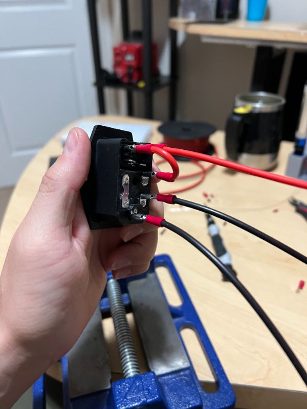
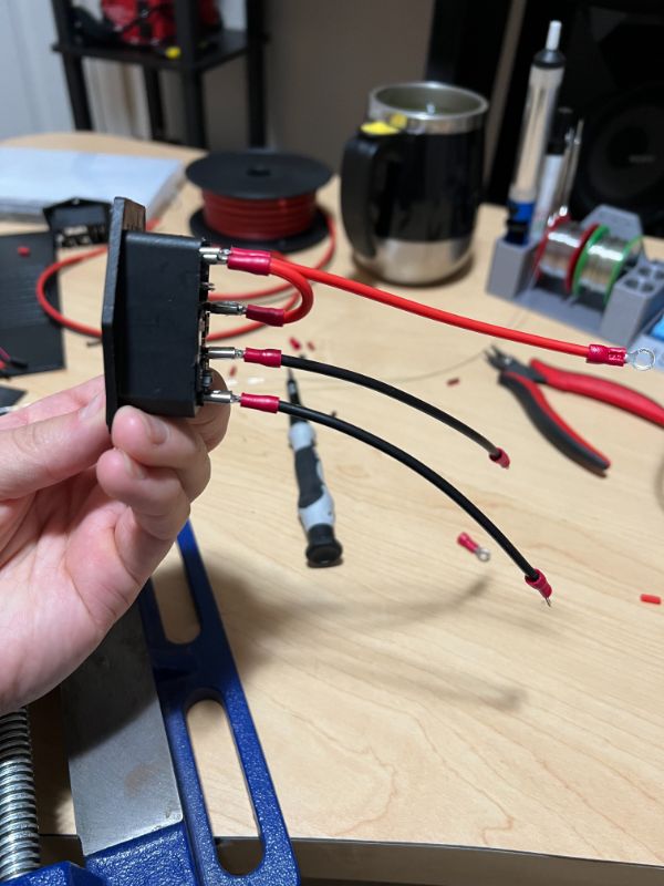
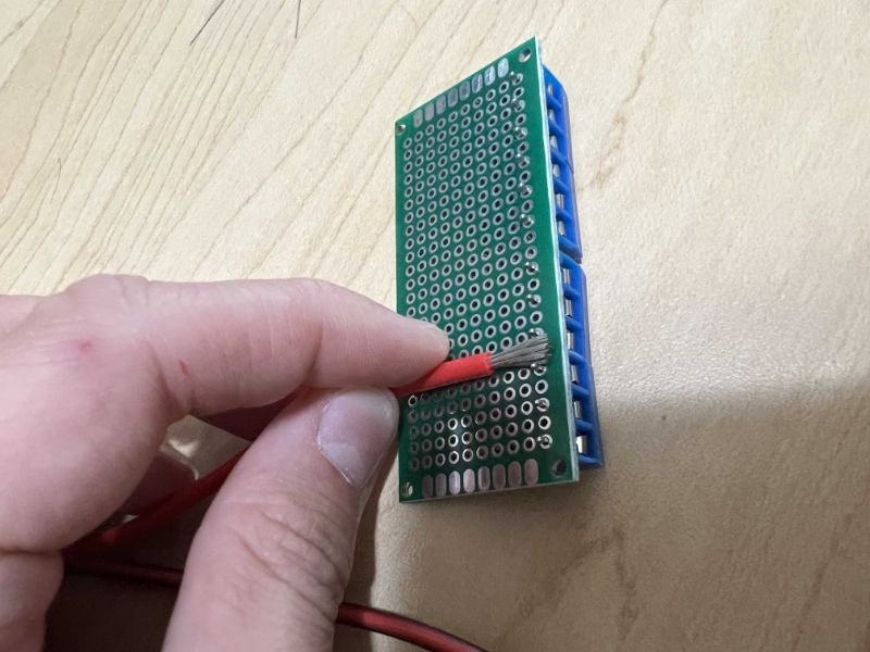
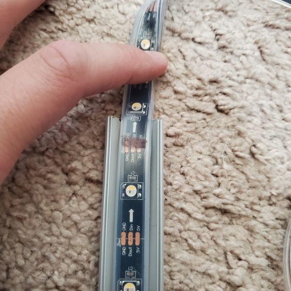
The strip comes in a watertight silicon sleeve and has terminals at both ends
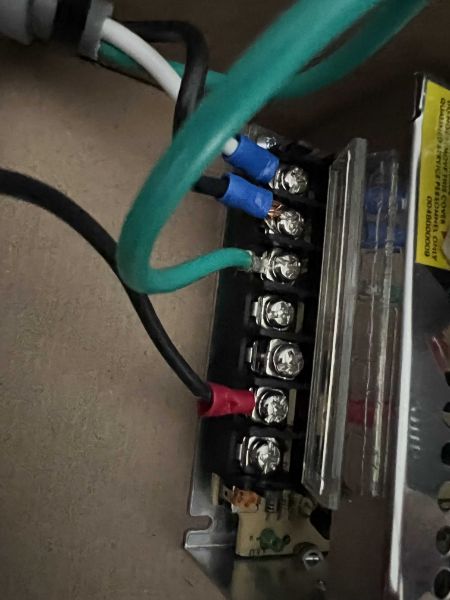
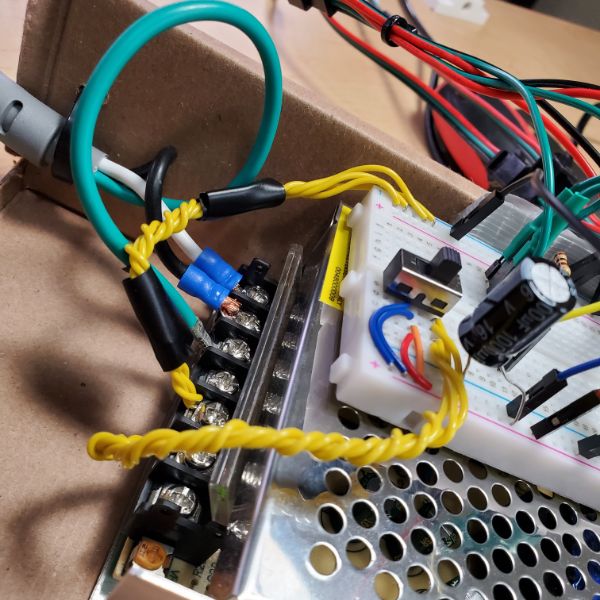
The terminal has a power wire, a ground wire, and then a 2-pin JST with the same ground, and a data wire. This is so I can connect one set to the power supply and the other to the microcontroller and have them both already sharing a ground.
Once I cut into the silicone sleeve, that’s something I can’t really undo. I’m not sure if I can take the strip out of the sleeve, or if that’s something I even want to do, but there’s a chance that could get ugly. Either way though, I need to get some LEDs off of this spool for testing. Even if I didn’t, I would eventually have to cut it for the desk mounting, so let’s figure that out
Both ends have the same terminals, so it doesn’t matter which end I cut
Actually, it does, because there’s a directionality to it. There is an arrow pointing across the strip that appears between each LED. So I’ll cut on the side of the arrows origin (X) —> ()
Sharpie sticks to the silicone pretty well. Comes off with some mild finger rubbing
Scissors can cut right through the silicone and the strip with ease. Not a problem, just take it slow and do it precisely
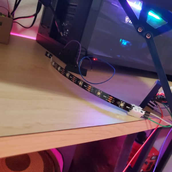
Stripped all four wires and crimped on some GPIO connectors to the strip of 10 LEDs. Time to connect to the arduino and test the Neopixel Library
The silicone sleeve can be easily cut by scissors, so extraction is pretty straightforward. The sleeve can be separated simply by pulling apart the seam on the side after a pilot cut. Since there are terminals embedded in silicone and a bunch of glue on one end, it’s not that simple to slide it out. But at the same time, there’s no way to get those terminals out of the silicone, so if you want the entire thing removed from the case you’re going to have to cut and resolder the terminal connectors anyway
More Rigging
I was eventually able to figure out while looking at the cyclone animation, why the pixel counts seem to be off. I have to increase them to a number higher than there are actually pixels on the strip I selected. It’s because the programming expects a RGB strip and the strips are RGBW and so they expect an RGBW signal. I haven’t looked that closely into it, but I noticed the Red/Blue/White pattern on Cyclone actually wrote a Green color to the pixel and then updated that same pixel to White before moving on. Which means that it’s writing that pixel twice and counting it twice in the total length of the strip.
This means that I can get the strips to function properly if I just multiply the actual pixel count by 4/3. That’s something I can fix later in software, but for now it means the strips are working properly.
I’m also noticing now that I have two strips of different lengths running concurrently, that two strips attached to the same data pin will simply perform the same commands in parallel, and mirror eachother. There doesn’t seem to be a way to convince one strip that it exists at the end of the other, or anything like that.
That means that in order for there to be two color commands, or two concurrent animations, there need to be two PWM signals coming from two separate pins on the uC. I still haven’t dove into the software so don’t know if that’s even something I can do with the libraries, but I don’t really see any reason why you shouldn’t be able to manage two PWM waves with on Arduino.
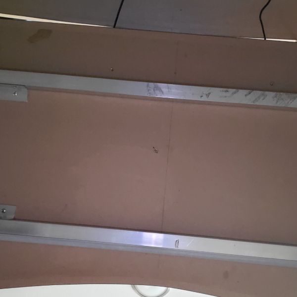
For mounting the back rail on the upper desk, the worst case scenario is that I have to undo all my cable management, take off the computer, and the component drawers, AND un-mount the monitor rack, take off the monitors, take off the upper desk, and THEN install the rails.
I don’t really want to wait until the next time I move to disassemble the desk and install the last piece of this thing, so I’m guessing the best available alternative is to use a large amount of the double-sided tape and carefully press it up to the desk. The tape performs pretty poorly when its exposed to air at all, but if both sides are flat and flush against a material it seems to last much longer. The only issue with this plan is that I don’t think I’ll be able to get it into position and adhered alone. The margin of space I have to work with back there is so low, I don’t think I can get it in without a second person, and without moving my 5-shelves in the corners.
What I can do though is work on the wiring harness. I’ve got a spool of 3-pin ribbon cable and some mesh cable sleeves. I need to figure out how to run two sleeves into eachother in an elegant way for it to look decent, but I don’t think that’ll be an issue.
The last thing I’ve got on my mind is the fact that when all the lights are full bright white, voltage drop occurs and the lights yellow and become a warmer shade. I’m not sure how to approach this other than just adding a secondary power injection to the lights on the far end of the strip. Turning up the source voltage might work but there will still be a relative temperature dip, and that has a higher risk of damaging the strips
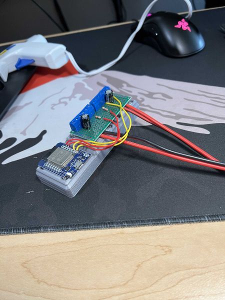
Along with all this, I need to pick a spot on the desk somewhere to put an enclosure that will hold both the PSU and the uC controlling the lights. The uC has to be WiFi enabled, so I was thinking an ESP32 or even just the Raspberry Pi long term. The only issue with that is, I want to run Home Assistant on the Raspberry Pi and it requires a hard ethernet port. I only have one running all the way upstairs for my computer, so the alternative would be to purchase PoE adapters and run either of those to the Raspberry Pi, but that seems a little excessive when I could just use the ESP32 local to the lightsbox and then keep the Pi on top of the Router.
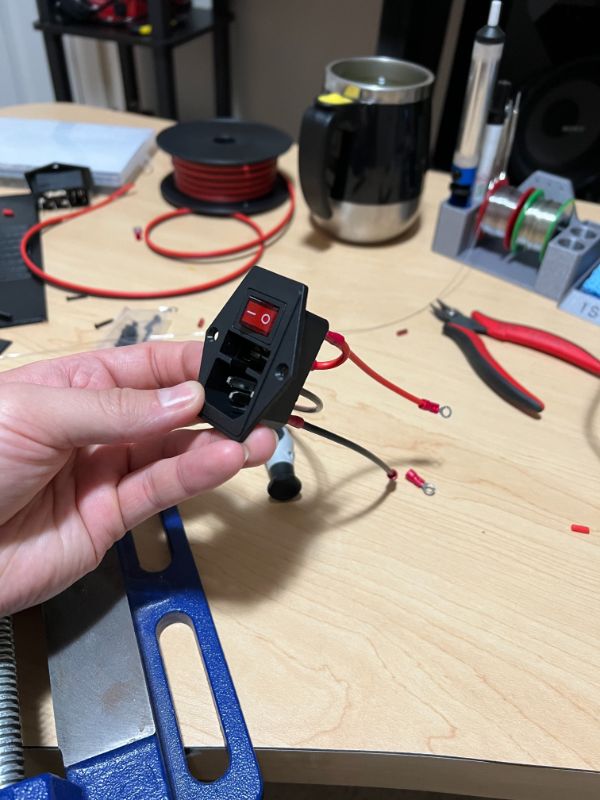
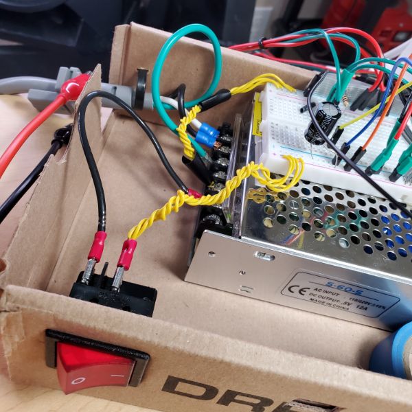
The PSU doesn’t have a female AC cable port, so I’m probably going to have to buy some of those snap-in ones and then design and print a box with a hole that size and shape, and a rocker switch. Just like ATX Power Supplies. But I’ll also need some pin exposure and some USB port Exposure in the case for the ESP32’s IO. I’m pretty sure you’re not supposed to connect a USB port and a Vin pin at the same time, so I would need a switch to disconnect the Vin pin that I can flip before connecting the USB port. That’s a small concern but potentially nontrivial
Since I’m using JST connectors, I could probably design the case to have four ports for JST connectors in the side, and have those connect internally to the ESP. That seems like the most elegant way to design the box:
Lightsbox Enclosure IO
AC Cable In
MicroUSB In
4x JST In
Removable Lid for debugging
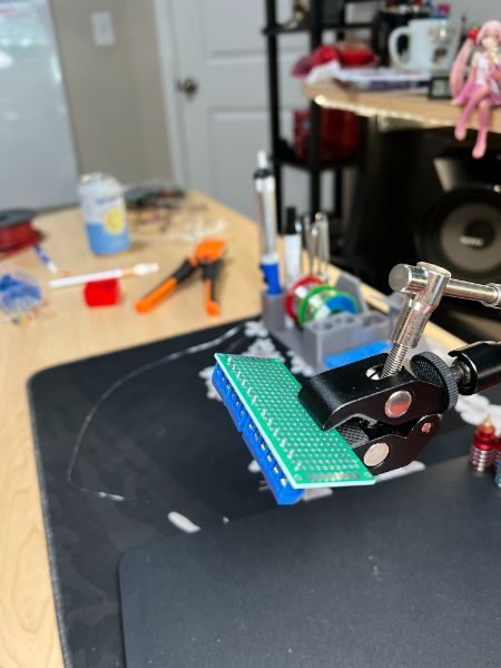
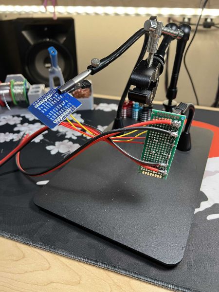
Small breadboard for ESP32 Circuit OR ESP32 Circuit on protoboard/PCB
I’m not quite ready to understand the library in depth, but if I can write a simple program to keep all the lights white, or some other color, that’s good enough for me.
Some good news is that after switching fromt he 5V 2A wall wart adapter back up to the 5V 12A Power Supply I bought, the voltage drop light warming is basically a non issue. I think the shade shifts a little bit but it’s nowhere near as noticeable
Spent about an hour just staring at the setup. I’ve got some plans for how to finish the mounting but I need an extra hand to get there
Next Steps
Finish Mounting backside rails, with diffusers and cut strips
Cut and solder wire adapters to length with installed rails going back to upper desk box spot
Confirm all 4 strips work on existing circuit, 1 PWM signal
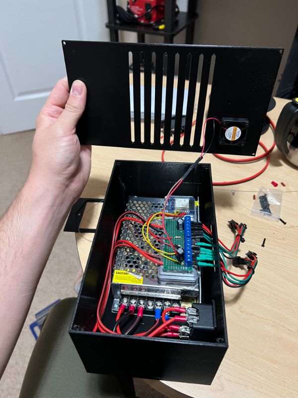
Design a box to contain the uC, PSU, and board
Finish a more permanent installation with the box and some cable management
Reprogram the Arduino
Re-reprogram the Arduino when a pattern change is desired
Wait until Breadnet 4 is set up, then swap the Arduino for an ESP32 controlled via MQTT
Rigging
Need some names for things
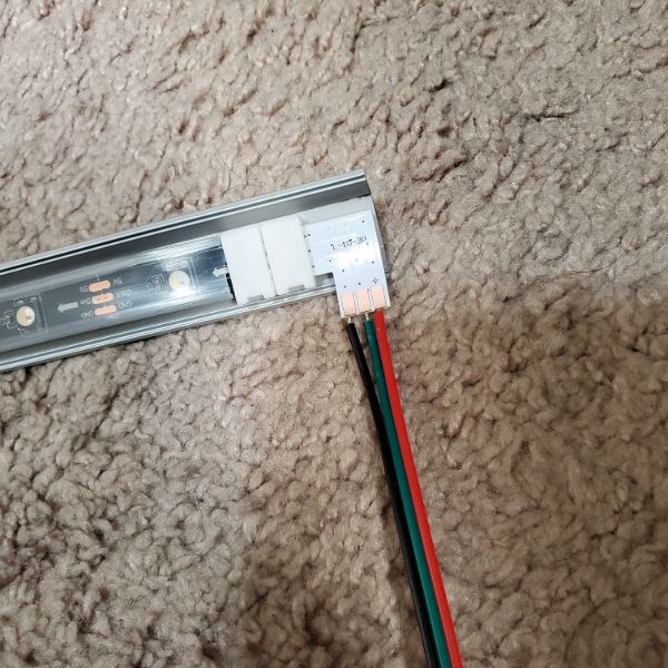
Right Angle Strips – Turners
latch Clamp bridge connectors – Bridges
Going to create a cable harness for testing. It’ll use a bridge to connect to the LED strip and on the other end of the bridge, a turner can be exposed to test DC voltage and read the PWM signal on the scope.
After that though, a better harness would be one that can supply the power and signals, rather than opening a trivial port to measure them (that already exists on the strip)
That’s what the JST connectors are for after all.
I’ll clamp down a female JST ribbon into the Bridge, and with the male JST I’ll solder some pins that can be strapped over to the PSU and Arduino. That way I can use the same harness for testing strips of 10 LEDs and full reels
JST pin leads can be made to fit under the Bridge’s clamps, but the insulation prevents the bridge latch from closing
After stripping the pin leads, they can’t be coerced into staying under the clamp, mainly because the individual wires’ adhesives are no longer connected. It seems like it’ll be easiest to just use one of the turners to create a solder pad point for the JST to connect to
Soldered together the harness, but now I need to cut a new strip of 10 LEDs. The strip has directionality, and the front of the existing test strip already has a fixed harness and the terminal waterproofing insulation, so I’m going to leave that one as is and make a second one. This will also be useful next for parallel signaling tests
There is a bit of internal friction when it comes to pulling the strip out of the silicone sleeve, but it’s not difficult at all. I’m guessing it’s a lot harder to put back in though.
Connected both 10 LED strips in parallel. As I expected, the strips simply synchronize as they’re both receiving the same 10-strip expecting signal.
This means that I can rig it such that the upper and lower desks have the exact same sequencing. And there can be two data lines working off of the same Arduino. To run two separate data lines is going to require some more creative programming than the example codes are going to provide though. I don’t think it’ll be that difficult for the Arduino to manage 2 concurrent PWM signals…
Connecting the main strip means setting up the 5V 12A DC Power Supply I bought.
I didn’t realize it didn’t come with an AC cable port, which means I have to screw down a spliced 3 wire AC cable into its terminals. Thankfully I already had one ready, but this also means I’m going to have to get creative with how this thing is housed and powered. I might end up buying my own AC cable female port and then embedding it in the 3D Printed hull of the Mega Lights Controller
I connected Test strip 1 to the main strip using a Bridge and started upping the light count. I can tell the programming updates when the lights blink onto a different color (using the Animation for fading). The limit seems to be around 80. Once I increase it past that, the Arduino takes the programming, but the behavior of the lights doesn’t change. Thankfully, I only need to run 60 LEDs at once on a chain, max. So it looks like that limitation isn’t really an issue, though it is inconvenient.
I changed it from the fade animation to the cyclone where it bounces back and forth and I was able to get it to chase all the way down to the end of the strip. But it has the same problem with counting the LEDs. There’s only about 140 on this piece, but it wouldn’t reach the end until I upped it all the way to 190. It seems like it might be counting some LEDs twice or something. There’s no glitches in the animation, so I’m guessing it’s just a software issue. It’s pretty confusing. I’m guessing the fade animation has a lot of information, since it’s constantly updating every LED in the chain, whereas the cyclone one only updates about 6 at a time
Software Test
The Default Neopixel library actually can’t work with the SK6812RGBW strips because they are only for RGB, so the instructions get corrupted as they’re passed on from the Arduino.
I’m using NeoPixelBus, which is a modified library that says it has support for the SK6812, and the sample codes are only 2 in number but they work fine. So this is something to go off of for now.
There’s only 10 lights. When I set the light count to 11, the 9th turns on, when i turn it up to 13, the 10th turns on. When set to 10, only 8 turn on. Strange
Turns out I was using Pin 13 and Pin 13 isn’t PWM, so moving it over to pin 9 solved that problem QUICKLY
Example “NeoPixelRotateLoop” is the best one to work off of so far.
I’m going to have to learn these things in pretty serious detail
“NeoPixelAnimation” Also works well
I need to test controlling two strips in parallel on the same data line, but with different lengths
apart from all the timing functions and stuff that’s the most important thing towards how the hardware will get wired
“NeoPixelCyclon” is my favorite by far
NeoPixelBus Library Dive
https://github.com/Makuna/NeoPixelBus/wiki
Might have to learn more about OOP for this
Want to take my time and really understand how to control these lights
LED Strip Research / Breadnet Project
Lab stuff, I have been kind of avoidant and dreading diving into the power supply. I feel like I don’t have enough time to get through the whole power supply series in just 2 weeks. Along with the Synth that I added on. If the Synth gives me as much trouble in layout as it did in Spice then I’m going to have an issue.
And if the Power Supply gives me as much trouble in either Spice or Layout as the Synth did in Spice, then I’m going to have another big issue. So I’m just generally not looking forward to getting started very much, so I spent a day researching some other stuff. Printer Upgrades, Desk Upgrades, Anti-Static for my chair, etc.
BOM
Parts will cost around $300
These aluminum channels are super expensive, so it’s in my best interest to go find the spares, if I didn’t throw them away.
But honestly, they looked super shoddy being constructed out of 1m segments
I might just drop the extra cash to get them 2m
Ideally, I would just buy 4 x 2m LED Strips, but that doesn’t seem to be an option
Even if I bought 7m at $18/m, that’s still $126, and then they look super shoddy and patchworked together. On top of multiple 10mm deadzones from adapters connecting together.
It looks like on two separate cases I’m spending an extra $50 just to make it look prettier
Comparison Video
https://youtu.be/QnvircC22hU
Power Consumption
Model
Voltage
Idle 0 LED
Single Channel per LED
RGB Channel Per LED
Single Channel, ALL 150 LED
RGB Channel, ALL 150 LED
PURE WHITE, ALL 150
SK6812
5
.83W
.05W
.148W
7.63W
14.4W
10W
Looking at the SK6812, as they are the only strip with a white pixel
Adafruit RGB Strip Product List
https://www.adafruit.com/category/183
Checking the data sheet, it looks like they have a max refresh rate of 30Hz
http://www.led-color.com/upload/201809/SK6812%20RGB%20LED%20Chip%205050%20Datasheet.pdf
Purchase Links
https://www.digikey.com/en/products/detail/adafruit-industries-llc/2828/5959337
https://www.adafruit.com/product/2824?length=1
Adafruit is the only reliable vendor for the SK6812 strips.
I’m looking at the black flex PCB with the minimal silicone sleeve. The 30/m strips run about $18/m. I am not sure how many meters I need though
Desk is divided into Upper Desk and Lower Desk
Both Desks have two aluminum rails, and LED Strips go on the out-facing sides for both rails for both desks, so four strips in total
Upper Desk Rail Length: 1.95m
Lower Desk Rail Length: 1.46m
Total Length to Cover: 6.82m
SK6812-RGBW’s are only in stock in 1m and 5m variants. I’ll need 2x5m
Project Steps
This whole thing should probably be a part of a larger project of setting up the Smart Home in earnest.
Which would involve me learning more optimal MQTT, Learning the ins and outs of Node-RED and HASS. Connecting my 3D Printer to the Breadnet
Some Security Oriented work
And then setting up a logging database like a weather station that can be repurposed into crickets in the future
Also includes ESP32 Over-The-Air Updates
Also Includes the Python GUI project for the mega lights
So
MQTT Dive
Node-RED Dive
HASS Dive
Weather Station
Mega Lights
Mega Lights GUI
ESP32 OTA Updates
OctoPrint
Network Security
ESP32 Low Power Deployment
Sounds like about 1 full month’s worth of work. So I’ll save that for later, after I’ve finished the 6 month to FPGA bootcamp
Wiring
I’m thinking I’ll have all the wires on the right hand side of the desk.
From the front-lower strip, I’ll run a mesh cable sleeve like the one I used on the 3D printer along the underside, collecting the back-lower strip, and then running down the underside of the inner leg.
For the upper strips, I’ll also have the cables connect on the right hand side, going from front to back
From there, I’ll have the lower desk mesh sleeve run back up and meet up with the upper desk sleeve, and connect them using a Y-adapter into one mesh sleeve.
Then I’ll run that Mesh Sleeve to the PSU/uC combo.
To minimize cable management, it seems like it would be best to keep the Power Lines and the Data Lines terminal in the same location, so the ESP32 and the PSU are going to have to be in the same place
Power Consumption
30 LEDs/m
6.82m
204.6 LEDs
0.148W/LED
204.6 LEDs x 0.148 W/LED = 30.3W
30.3W @ 5V = 6.1A
Conclusion: Get a 5V/12A PSU
Mounting
I’m thinking about mounting the power supply on the underside of the upper desk on the right hand side, but I’m not sure that’s the smartest approach.
If I’m using a ESP32, The input voltage should be 3.3V-3.6V, but it has a regulator to handle 5V, or up to 6.5V I think.
The input output pins are NOT 5 Volt tolerant.
I think the safest approach would actually be to use the 2nd buck converter from the pack of 2 I bought for the 3D Printer, and set that to ~3.5V so the ESP has a buffer and a layer of extra regulation. Is that how power supplies work? Not sure. But I’m pretty sure that’s safer than powering the ESP32 directly from the PSU.
So if I’m putting an ESP32 and a PSU and a Buck Converter all in the same place, it wouldn’t be very convenient or elegant to mount all that on the underside of a piece of wood 4 feet off the ground.
I’m thinking the best option would actually be to run both cable mesh sleeves down to the floor and then just fashion an enclosure for the 3 Devices.
In that case, it would be simple enough to print an enclosure for everything.
Dimensions of the PSU are approximately that of Carl Jung’s Man and His Symbols
6″x4″x2″ roughly
6.26″ x 3.86″ x 1.65″ exact
Putting it in a 3D Printed Enclosure on the floor would also allow me to skip the whole Y adapted Cable Mesh Sleeve Problem as well.
This would also be a good opportunity to put my modeling and printing skills to good use in an electronics project for the first time
System Scheme
4 RGB LED Strips
Power Connection to PSU
PSU Powered From Desk Power Grid
Data Connection to ESP32
Look into OTA Uploads for ESP32?
ESP32 using NeoPixel Library
Connected to Breadnet via MQTT
MQTT hosted via RPi using HASS
ESP32 receives commands over Breadnet-MQTT via a Python Desktop GUI
PC
There are also RGB LED Strips specifically for PCs that can plug into slots on the MOBO, if that’s an angle I want to take. I kind of like it how it is now though.
If I’m going to put any more money into the PC, it’d be for a Noctua Intake/Exhaust Fan since there’s no net airflow betwen the PC and the room
https://youtu.be/8guzWUeQ3FQ
Future Upgrades
Eventually, I could replace the PSU with a 5V 12A one that I designed myself, but I’m not sure how far away that could be.
I’m also thinking about trying to sync it with keyboard presses or with audio
At minimum though, I want to create patterns that can be called at the press of a button off of the GUI
Ideally, I’d have individual control over the LEDs, which would mean the GUI would have a visual representation of each LED’s current status. From there, I could select an individual LED and set its color
2022-g
Mega Lights 2
Order more JST-XH connectors (not plain JST)
Find a Female AC Cable Port for the box?
Back upper strip looks great, installing lower back strip now
Need to get a count
LIGHT COUNTS
UPPER DESK: 58
LOWER DESK: 43
2022-h
Mega Lights 2
Note
Finally got them working
two channels, individually addressed, with my arbitrary control over them
Now a question of, how do I take notes on, and store code and code fragments and pseudocode in treesheets?
Anyway, here’s the working twinsig.ino
twinsig.ino
#include <Adafruit_NeoPixel.h>
#define PIN1 9
#define PIN2 10
#define UPPIXELS 58
#define DOWNPIXELS 43
#define DELAYVAL 50
Adafruit_NeoPixel upline(UPPIXELS, PIN1, NEO_GRBW + NEO_KHZ800);
Adafruit_NeoPixel downline(DOWNPIXELS, PIN2, NEO_GRBW + NEO_KHZ800);
void setup()
{
upline.begin();
downline.begin();
upline.show();
downline.show();
}
void loop()
{
// upline.clear();
//downline.clear();
for(int i=0; i<UPPIXELS/2; i++)
{
upline.setPixelColor(UPPIXELS/2+i, upline.Color(0,0,255,255));
upline.setPixelColor(UPPIXELS/2-1-i, upline.Color(0,0,255,255));
upline.show();
if (i < DOWNPIXELS/2+1)
{
downline.setPixelColor(DOWNPIXELS/2+i, downline.Color(0,0,255,255));
downline.setPixelColor(DOWNPIXELS/2-i, downline.Color(0,0,255,255));
downline.show();
}
delay(DELAYVAL);
}
for (uint32_t firstPixelHue = 0 ; firstPixelHue >= 0 ; firstPixelHue += 256 )
{
for (int i=0 ; i < UPPIXELS ; i++)
{
uint32_t pixelHue = firstPixelHue + (i * 65536L / UPPIXELS);
upline.setPixelColor(i, upline.gamma32(upline.ColorHSV(pixelHue, 255, 255)));
if(firstPixelHue>65536) {firstPixelHue=0;}
}
upline.show();
delay(5);
}
}
That’s kinda funny the way it blocks it out. I could probably change the way I format the code to make it transfer in and out of treesheets better
Pushing it into, and then pulling it out of TreeSheets also eliminates a huge amount of unnecessary spacing…. There are ramifications here.
Software
Adafruit Library
So the main problem was just declaring the instantiation of the Adafruit_NeoPixel object. It requires a number of pixels, a pin, the LED type, and the frequency.
Specifically, I needed to declare it as NEO_GRBW
I did notice that because the lower desk has 43 lights, and the upper has 58, that means i have to code the upper half for an even number and the lower half for an odd number
for(int i=0; i<UPPIXELS/2; i++)
{
upline.setPixelColor(UPPIXELS/2+i, upline.Color(0,0,0,255));
upline.setPixelColor(UPPIXELS/2-1-i, upline.Color(0,0,255,255));
upline.show();
if (i < DOWNPIXELS/2+1)
{
downline.setPixelColor(DOWNPIXELS/2+i, downline.Color(0,0,255,255));
downline.setPixelColor(DOWNPIXELS/2-i, downline.Color(0,0,255,255));
downline.show();
}
delay(200);
}
Void Setup
strip.begin();
Starts up the strip, mandatory
strip.show();
Renders current strip output, useful during setup to render an empty array
strip.setBrightness(n)
0-255, sets default brightness for all colors unspecified.
If you don’t use the HSV and define a color tuple, this will apply
Void Loop
Functions
strip.fill([colortuple])
strip.setPixelColor(i, Color(r,g,b,w))
Sets the pixel color.
Note you can’t use capital S in set
If R=G=B, then it’ll render white
But this white will be a classic RGB white, so it’ll look blue
It draws more power than necessary and is prone to the highest voltage drop, and thus redshift
One trick to make the default 0,0,0,W colder is to run 0,0,B,W. Works great, and voltage drop doesn’t seem to be a huge issue
strip.show()
Renders the output
strip.ColorHSV(H,S,V)
hue, saturation, value
this function’s output acts as the color tuple. It just converts the HSV inputs into an RGB output.
It takes a hue value of 0-65536. It’s not strict though, it’ll just roll over.
True Red is in the dead-center of this range
Saturation and Value(aka Brightness) both range 0-255
strip.gamma8([colortuple])
strip.gamma32([colortuple])
Takes in a color tuple and gamma/brightness corrects it. It generally makes animations that scale brightness smoother
Animation Structures
colorWipe
void colorWipe (uint32_t color, int wait)
{
for(int i=0; i<NUMPIXELS; i++)
{
pixels.setPixelColor(i, color);
pixels.show();
delay(wait);
}
}
whiteOverRainbow
int snakeLength = 10;
int snakeSpeed = 20;
int headPos = snakeLength – 1;
int tailPos = 0;
uint32_t lastTime = millis();
uint32_t firstPixelHue = 0;
void setup()
{
upline.begin();
upline.show();
}
void loop()
{
if(snakeLength >= UPPIXELS) {snakeLength = UPPIXELS – 1;}
for(int i=0 ; i<UPPIXELS ; i++)
{
if ( ((i>=tailPos)&&(i<=headPos)) || ((tailPos>headPos)&&((i>=tailPos)||(i<=headPos))) )
{
upline.setPixelColor(i, upline.Color(0,0,0,255));
}
else
{
int pixelHue = firstPixelHue + (i*65536L/UPPIXELS);
upline.setPixelColor(i, upline.gamma32(upline.ColorHSV(pixelHue,255,255)));
}
}
upline.show();
firstPixelHue += 40;
if((millis() – lastTime) > snakeSpeed)
{
if(++headPos >= UPPIXELS) {headPos = 0;}
if(++tailPos >= UPPIXELS) {tailPos = 0;}
lastTime = millis();
}
rainbowFade
for (uint32_t firstPixelHue = 0 ; firstPixelHue >= 0 ; firstPixelHue += 256 )
{
for (int i=0 ; i < UPPIXELS ; i++)
{
uint32_t pixelHue = firstPixelHue + (i * 65536L / UPPIXELS);
upline.setPixelColor(i, upline.gamma32(upline.ColorHSV(pixelHue, 255, 255)));
if(firstPixelHue>65536) {firstPixelHue=0;}
}
upline.show();
delay(5);
}
stripFlare
for(int k=0 ; k<256 ; k++) //pulse filler
{
pixels.fill(pixels.Color(0,0,0,W);
pixels.show();
delay(10);
}
for(int k=255 ; k>=0 ; k– ) //pulse drainer
{
pixels.fill(pixels.Color(0,0,0,W);
pixels.show();
delay(10);
}
Hardware
There was an issue with the lower front strip glitching out, shorting, and turning off the other strips as well as itself
I figured out it was because the bridge clamps were weak and the copper was dented in the strips
I fixed the issue by just soldering the two together and then clamping it closed.
I also centered the lights more perfectly.
I used some alligator clips and tested the secondary injection of the 5V onto the far side of the front bottom strip and it improved voltage drop noticeably, but not enough to justify adding that many more wires to the system.
I got the dual signals working, and it was so easy, I’m pretty sure I could get all 4 strips working independently on a single microcontroller
Next Steps
The next major step is to get a twin-tailed pulse to jump from the center
Once I get that moving, I’d like to build it into an interrupt routine
If I can independently animate/set the background from the interrupt pulse in an elegant way, then I’m set
After that, it’ll be time to set up the ESP32 and Breadnet/MQTT
That way I can trigger the ISR over MQTT using my phone, a keyboard stroke, etc.
I also want to set up a useful interface for specifying a specific position in the array and overriding the pattern with a static light at a higher priority
It seems like there might need to be multiple priority levels and some sort of memory state for the array of tuples that can be stored, pulled, reverted, edited, etc.
From there I can execute on some other ideas I have:
Brightness throb matched to song tempo
Heartbeat matched Center Pulse
Specific Status Indicator lights
Binary Clock
With Specific Status Indicator Lights (SSILs) the desk can actually communicate a large amount of information with varying priorities about other projects/sensors/devices throughout the house/network
Not sure how useful that could be, but a starting point would be confirming garage status or something
2022-j
Mega Lights 2
Arbitrary control of 1 LED on ESP32
Equivalent Light Strip Script on ESP32
Design Lightsbox around ESP32 prototype+Color Text
Hack into my lightbulbs and control them with Node-RED
ML2 – Mega Lights 2
ESP32 Neopixels
ESP32 works perfectly fine with copy/pasted code from the Arduino sketch for Neopixel control, which is good news
Unfortunately, the ESP32 can’t take 5V input. I think the max is 3.6 – 3.9V, so I need to find a way to lower the input voltage of the 5V supply.
I’m guessing that a level shifter is for control signals and not really for power transmission, so the best solution is probably to just use the other buck converter from the pack of two I bought for the old 3D printer
As I expected, the rainbow pattern is working, but it’s choppy and slow with mqtt running
I disabled MQTT’s client loop and just ran the pattern and it was nice and smooth again.
Having i print millis() after each light update cycle, it looks like they’re about
163 ms Light Cycle without MQTT
164 ms Light Cycle with MQTT
73 ms Light Cycle on Arduino
I think I might’ve just had the hue shift value at 32 still…. and that’s why it was choppy
ohh
I took .show() out of the loop so it doesn’t show after each pixel.
It seems like show is the longest part of the function, it’s so much smoother afterwards
I don’t remember messing that up, but now with show outside its
3 ms Light Cycle with MQTT
Verify ESP32 working with Buck Converter
I can’t tell if I should be plugging into VCC or 3.3 on this board’s pinout
I bought it on Aliexpress so its pinout doesn’t match anything else and I can’t really follow the traces visually
I’ve got plenty to spare though!
Melted Wires
There’s some intrinsic heat generated in the jumpers. They’re not meant to carry 2.5A.
Well, it kind of seems like they can handle it, but they used the breadboard as a heat sink
That, in combination with the breadboard being ON TOP of the power supply, and the voltage and ground wires being side by side, combined to make a very slow breadboard melting device.
Running it with just one or two branches of lights results in a tangible warmth coming from the wires. So, I need to do something about that
The best idea I can come up with as a temp fix right now is to just make sure the power and ground rails are on opposite sides of the breadboard, and then run multiple jumpers for each to diffuse the current.
And then tap them in at different points along the power rails, of course
Notes
i have all of the power running through a single jumper wire
and it melted the breadboard
so i need 2 wires
about 30W of energy if all lights are on, but it gets warm and compliant with just 1/4th of them
The lights flicker every now and then, not sure why
I can also distort the signal by putting hands on the wires
I’m guessing this whole thing just needs to be wired a little more securely
Lightsbox R-1
Took out the buck converter
It turns out that the ESP32 takes in about 5V from the USB when programming it, so why shouldn’t it be able to take 5V from a power supply?
I found that using the buck converter and inputting 3.3V actually interfered with signal integrity
I also figured out that the current limiting resistor of 400-600R is too high for the ESP
If you try to connect all 4 strips to a single PWM pin, the current draw is too much and the signal collapses. I had to reduce the R all the way to 100 for the signals to not crash
To in summary, increased input voltage to 5V (4.95) and decreased output resistance to 100R
I also found that braiding 4 solid core jumpers together solved most of the overheating problem. I still wanted a switch, so I inserted a breadboard switch, but it quickly became too hot to touch with all the current running through it, so I replaced it with one of the chunky breadbox switches I Had leftover. I had to crimp some terminals to get it installed but it was worthwhile and now nothing seems to overheat
I melt-tested by turning all the lights up to 255,255,255,255, which draws an insane amount of current.
The hottest thing in the box is actually the power supply at that point.
The connection between the crimped terminal and the breadbox switch that runs to the breadboard seems a little shoddy. I kept touching it to see how warm the braided cables are but it caused the lights to flicker off momentarily. If I do it too much and it turns off for too long the ESP also powers down.
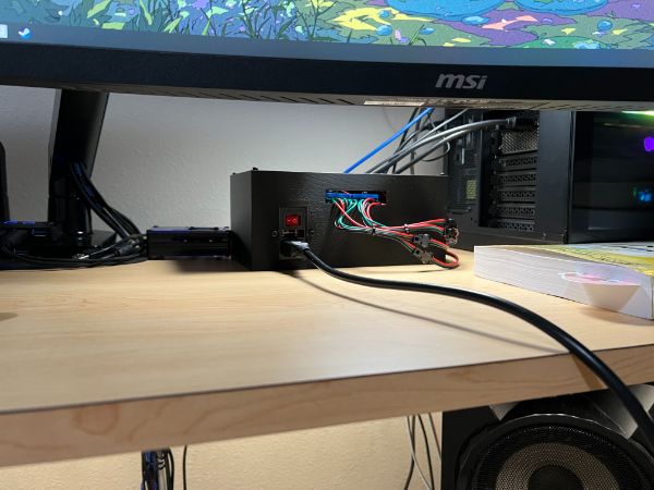
For now, the lightsbox seems safe enough and I should be clear to move onto other things while enjoying the first practical application of breadnet and the fancy lights I put so much time into
I noticed a stuttering issue that I thought was due to the resistor being too high still, but it was regular. I correctly guessed that sometime during the mqtt check loop it defaults to light status = 0 and clears the pixels. I turned that if/else into an if/if. So technically there’s no default command for the lights anymore, which got rid of the stutter
Lightbox R0
AC Power Port
https://www.amazon.com/button-Adapter-Connector-Socket-MXRS/dp/B082ZFRV1B/ref=pd_day0fbt_img_sccl_1/144-7350682-5806604?pd_rd_w=7X3VD&pf_rd_p=bcb8482a-3db5-4b0b-9f15-b86e24acdb00&pf_rd_r=SX1JSAA9SA8365BYANJM&pd_rd_r=2a07e6ad-f631-4baa-9e80-f91427ab0b17&pd_rd_wg=Swye7&pd_rd_i=B082ZFRV1B&psc=1
Comes with a switch! $8
PCB
Could design a PCB that has a buck converter, the necessary circuits, and the EPS32 in it all in one
The weakest part of the circuit right now is the fact that all the power coming from the power supply is carried to the breadboard by a single jumper
So the best way to fix that is to get thicker wires, or more wires
If i had a PCB, I could make some large heat dissapation zones and then have similar screw down terminal clamps
I could probably do that with a proto board
Cables
Thicker cables are needed
Maybe 16AWG to be safe?
https://www.amazon.com/dp/B079CFZZYS/ref=sspa_dk_detail_5?psc=1&pd_rd_i=B079CFZZYS&pd_rd_w=yyeqR&pf_rd_p=0c758152-61cd-452f-97a6-17f070f654b8&pd_rd_wg=esIgs&pf_rd_r=0Z2ETXA7DD813T1W40HE&pd_rd_r=c0528a0e-5856-4ea6-b460-eca03ea59510&s=electronics&spLa=ZW5jcnlwdGVkUXVhbGlmaWVyPUEyUEJPMVRRWkFBQU1QJmVuY3J5cHRlZElkPUEwODg0OTQyM01RREdGUVoyQlhWSSZlbmNyeXB0ZWRBZElkPUEwOTg0NzgwM1ZTSjlNV0xNVERNTyZ3aWRnZXROYW1lPXNwX2RldGFpbCZhY3Rpb249Y2xpY2tSZWRpcmVjdCZkb05vdExvZ0NsaWNrPXRydWU=
Also need some terminal blocks to clamp down in that case
The power rails only go to the strip and the ESP32 anyway!
More specifically the buck converter
2022-k,l
Lightsbox
Try not to break it or burn the house down
Start Designing a PCB for it
Start Designing a new box for it
2022-m,n,o
ML2
Code for split PWM signals for top and bottom
No need for four individual signals
This will also allow the current draw to be distributed across 2 pins, which has been stressing the ESP
Update ESP Module Code for split signal
Update Breadnet Backend for split signal
Re-arrange breadboard
move around signal wires and light channels
potentially add new resistors to limit current
Confirm system works as intended
Design Protoboard for system including newer high AWG wire running from switch
Sketch out 3D Printed box based on current cable management and UI
Include 2 back ports for upper and lower desk signaling
Mounting Slots for PSU
Include Female AC Socket, Order Part
Double check connection integrity at strip
Fix shitty power switch terminal connectors
Include USB port and pin header exposure for ESP32
2022-p
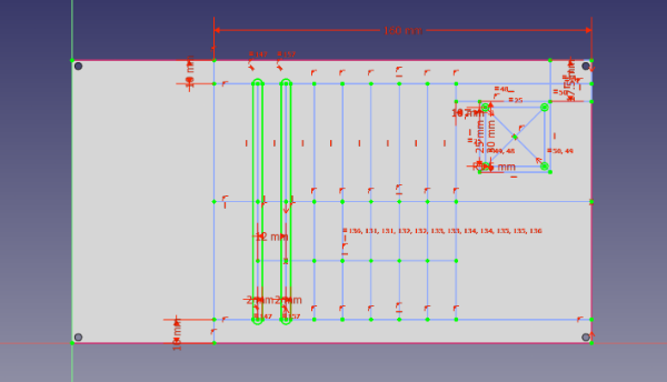
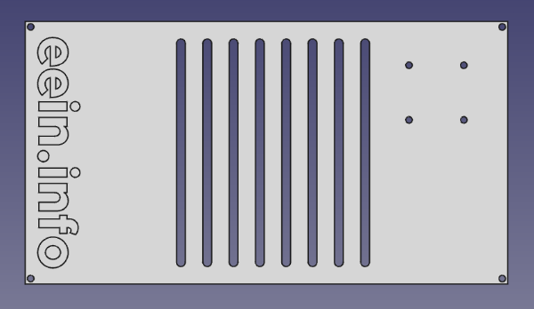
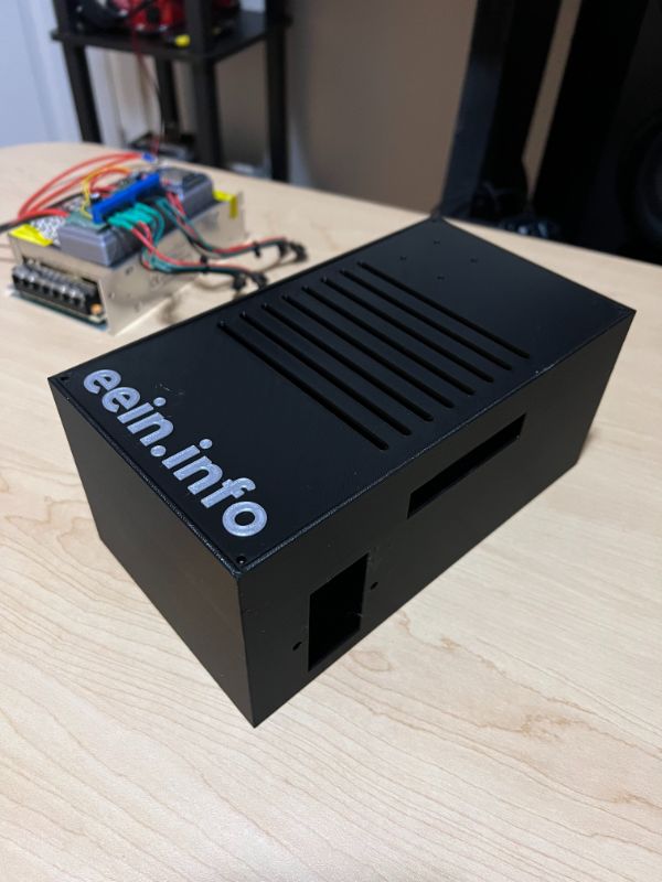
ML2 – Lightsbox [DONE!]
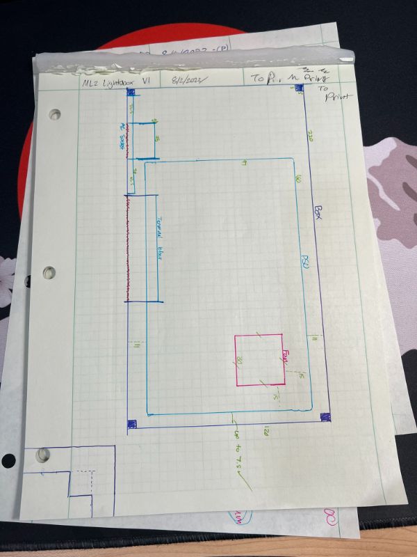
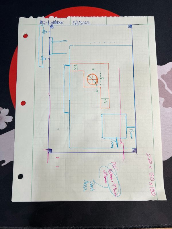
Dimensions are 9x5x4″
x 25.4
228.6
127
101.6
228 might be too big for build dimension
Thankfully I don’t need ALL that space
See if 210 or 200 works
200 should work fine
200 x 130 x 100
Need Holes over top to vent for PSU
Need Screw Mounts for PSU fan
Need 2 Cable Ports for Upper and Lower Lights
Need Port for AC Cable Input
Need Room for screwholes for mounting lid on
Doing a design similar to noise toaster case with a lidded box
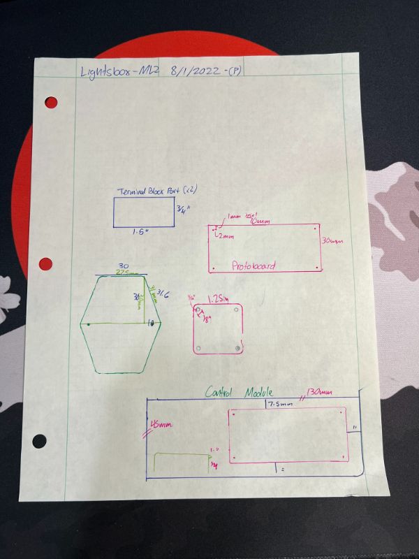
Measurements – First Pass
Fan
1.25″ square
Holes are 1/8″ inset 1/16″
Actually
30mm total
25mm center to center of holes
PSU
AC Socket
Start with a 30mm x 30mm rectangle
Extend 10mm
Hypotenuse should be 31.7mm
Hole center inset 4mm
3mm hole
Control Board
3×1 Gridfinity
45mm x 130mm
Protoboard
70mm x 30mm
1mm inset 2mm holes M2
Inset from control board 7.5mm on 3 sides
Terminal Block Port
2 of them
.75″ x 1.5″
Measurements 2
Body
Interior
220x120x100
Exterior
225x125x100
2.5mm walls
5mm square screw slots
PSU
97x160x43
AC Socket
70mm square
60mm tall
10mm triangle extension
30 bottom edge
20 from center holes
4mm diameter holes
inner rectangular hole 28.5×55
Fan
30mm square
25mm center to center for fan holes
fan holes 3mm diameter
Terminal Block Port
70×15 Wall hole
starts 75mm from the open wall
65mm up from the floor
Lid
2.5 thick
220x120x2.5
3mm diameter holes, inset 2.5mm
Airflow slots not speckled holes but
||||||||||||| vent lines
Prints
After one print, both the fan mount and the AC Socket’s measurements were off
So you know I had to break out the Calipers on em
Changed AC Socket’s holes to being 19 mm away from center line
Measured Fan’s dimensions to be 30mm total, 25 mm line between circle centers
Now to design the actual box
AC Socket is perfect now
Fan holes are good enough
Designed both box and lid
lid 4.5 hours
box 13.5 hours
Print Measurement References
M3
Shaft
2.95mm
Hex Nut
5.55mm Hex OD
6.41mm Hex OD
corner to corner
2.6mm Depth
Bolt Head
5.60mm Circ OD
midpoint to midpoint
3.15mm Depth
Sketcher Keyboard Shortcuts
Carbon Copy
C then C (don’t press at the same time)
Close Shape
Ctrl + Shift + S
Constrain circle or arc
Shift + R
Copy
Ctrl + C
Connect edges
Ctrl + Shift + K
Constrain Angle
A
Constrain coincidently
C
Constrain Distance
Shift + D
Constrain Horizontal Distance
Shift H
Constrain Vertical Distance
Shift + V
Constrain Equal
E
Constrain Horizontally
H
Constrain Internal alignment
Ctrl + A
Constrain Parallel
Shift + P
Constrain perpendicular
N
Constrain onto object
Shift + O
Constrain Symmetrically
S
Constrain tangent
T
Constrain vertically
v
Create fillet
F
Create Line
L
Create rectangle
R
Extend Edge
T then E
Extend geometry
X
Move
Ctrl + M
Hide/Show internal geometry
Ctrl + Shift + E
Select conflicting constraints
Select constraints
Ctrl + Shift + C
Select elements with constraints
Select the horizontal axis
Ctrl + Shift + H
Select Origin
Ctrl + Shift + O
Select redundant constrains
Ctrl + Shift + R
Select the vertical axis
Ctrl + Shift + V
Toggle construction geometry
C then M (don’t press at the same time)
Trim edge
T then R (don’t press at the same time)
Print went great
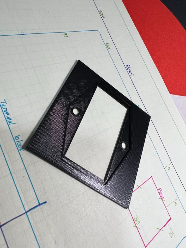
Everything fit exactly as it should have.
Only one thing went wrong really: I didn’t even realize that there was no ventilation for the fan. Just four holes to mount it but it doesn’t have any intake lol
Nobody called me on it and I didn’t notice until I had already screwed everything in
Box works great now. had to solder the L connectors together so the strips don’t lose signal integrity over the most gentle mechanical disturbance. I technically can’t take them apart that easily anymore, but that just means some extra cable will hang on the desk when it’s moved (which is how I moved it anyway)
Box feels like it’s way bigger than it needed to be and I feel like I should’ve found a way for breadnet to fit in there, since ML2 and Breadnet are both going to be in the same place anyway (on the desk, next to the tower)
If I really wanted to integrate, I’d just put Breadnet inside my PC tower lol
ML2 is now officially done. Anything else I’ll do with this project will be on the software side through Node-RED manipulations.