
10/10/2022 – 11/6/2022
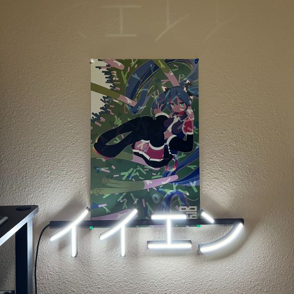
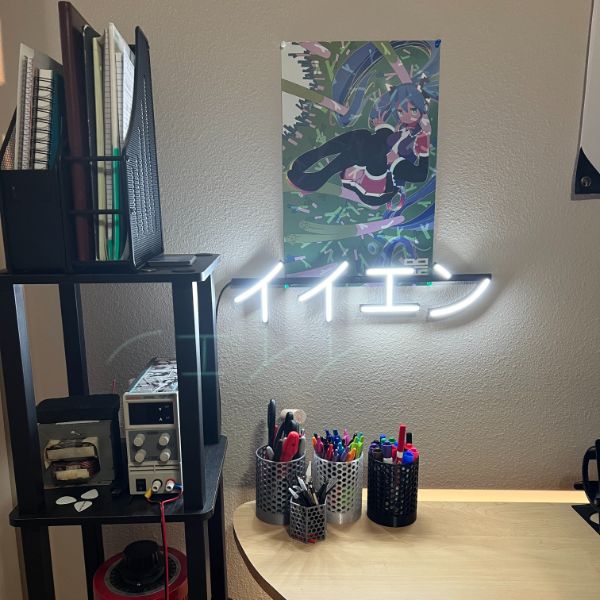
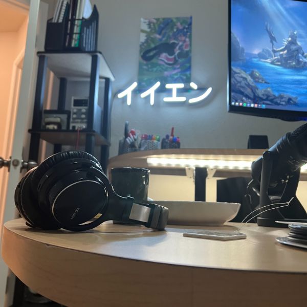
Summary: Spent the last month working out how to make custom LED neon signs based on 3D Printed channel structures. I originally was looking into the Acrylic/CNC route but decided I could probably make it work with just 3D Printing. The process is pretty well fleshed out at this point and I’m preparing to start taking orders and selling them, which is exciting. I’ve gotten a lot of positive feedback on the signs so far and have done a lot of iteration in order to make it look as good as possible. I learned how to use Fusion 360 as well and it is dramatically faster and easier to use than AutoCAD.
Not lab related, but I’ve spent a lot of time the last few weeks entering underlines, notes, annotations, etc. from books I’ve read the last few years into my master Library Treesheets file. Moving forward I’ll be focusing on trying to streamline this little side business and see if I can turn it into a new source of income to help fuel the lab and other projects moving forward.

Personal MBA Notes
Value Creation Chapter
Ten ways to evaluate a market
score the idea with angel
Value type 1 – product
Iteration CYcle – wigwam method
Feedback
9 Economic Values
Relative Importance Testing
critical assumptions
develop these with angel, pursue hypotheticals
shadow testing + minimum viable offer
Project Flow for remaining Sprints
UVWXYZ
6 Sprints, 3 Months
Project List
Ch 2 Review
Ch 3 Readthrough
DIY CNC
3D PRINTED CNC BUILT FROM SCRATCH CUTS METAL
https://youtu.be/ctyLjOHg7Ag
Crazy ass video. This guy is next level
Would have to spend a bunch on tools and materials
Mill Right Mega V Router
https://millrightcnc.com/product/millright-cnc-mega-v-router-bundle/
$1900
Watch This Before You Buy A Desktop CNC Router
https://www.youtube.com/watch?v=Ujt3h8TlMxE
Recommends a budget of about $2500 for the machine and $3000 overall
Thingiverse TopsCNC 3D Printable
https://www.thingiverse.com/thing:3813481
Home PCB Milling
Laser Cut/Engraving
Wood Cut
Acrylic Cut
Plasma/Bluetooth Speaker
Breadnet Macropad
Acrylic Neon Signs
LED neon Sign with clear acrylic backer
https://youtu.be/ZBdEyyzliAw
Inner groove for neon stripe
3mm end mill
Cut out the acrylic,
cut a shallow channel in the middle for the neon strip
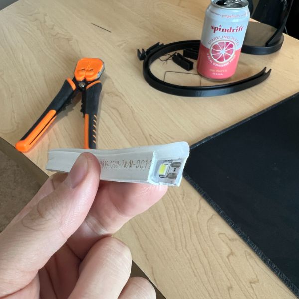
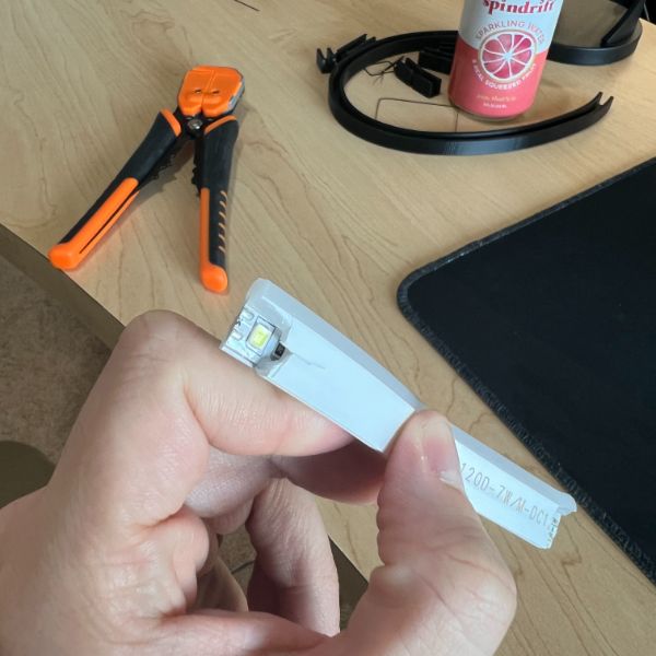
lights seem to be a very thin LED based, but much smaller than what I’m used to working with
Designed with Illustrator
How To Make a Neon Sign
https://youtu.be/kPG_N9BZHQQ
Good Video
Flexible Neon Signs
Flexible Neon
Pretinned Cable Strips
It’s called “Neon Flex
Need to de-static the acryllic after removing the adhesive protection layer
Clean with antistatic cleaner or cloth
The static will shift the glue around, mark and smear the acryllic and ruin the design
Drill wire holes into the acryllic
The Flex Neon IS the strip, not just a diffuser
Use adhesives to sustain strong kinks/bends in the Flex
Flex neon has a 10mm cut interval
Most have 25mm cuts
Exposed Soldering point is two thick copper channels that seem to run throughout
MitreBond glue/pen combo
Wipe the pen on the back of the Flex, then small drops of glue on the channel
Bonds instantly
Tin the soldering point on the flex
Acrylic recommended 5-10mm thick min
👌 NEON LED LOGO⚠️3D PRINTED!! / PETG Filament
https://youtu.be/ekQ3Puw_kjY
Looks pretty easy
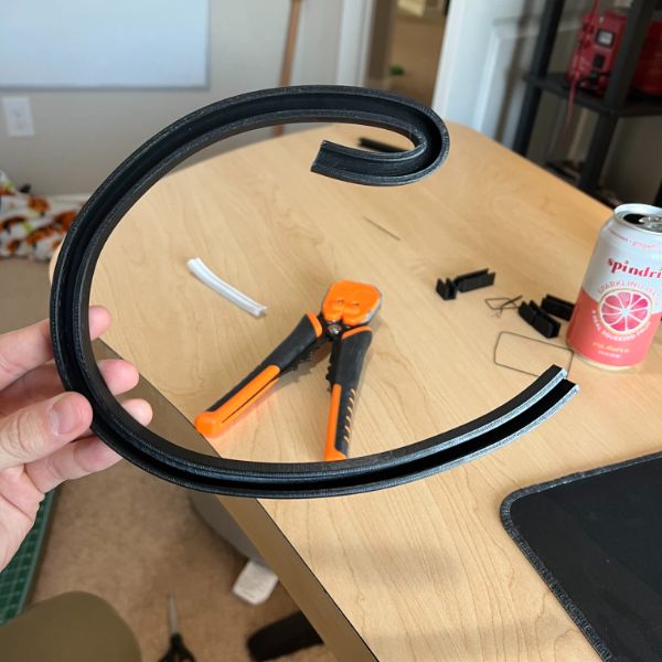
This one created the channels using PETG Filament
I can do that basically today
Let’s see if I can justify buying some Neon Flex for tomorrow delivery
Acrylic is the name of the material
Plexiglass is the name of the brand
Plexiglass vs Acrylic
https://maxplastics.com/acrylic-vs-plexiglass-a-comparison-guide/
Types of acrylic sheets
Cast acrylic sheet
Continuous cast acrylic sheet
Extruded acrylic sheet
Sign grade acrylic sheet
Marine grade acrylic sheet
Acrylic mirror sheet
White acrylic sheet
Abrasion resistant acrylic sheet
Solar tinted acrylic sheet
Textured acrylic sheet
Types of polycarbonate sheets
Clear polycarbonate sheet
Bulletproof polycarbonate sheet
Abrasion resistant polycarbonate sheet
Anti-static polycarbonate sheet
Mirrored polycarbonate sheet
Colored or tinted polycarbonate sheet
Applications of polycarbonate
Polycarbonate is used in making molds for casting urethane and silicone
It is used for making industrial machinery guards
In the automobile industry, car makers use it extensively to make different kinds of vehicle parts such as windshields and headlights
Polycarbonate is also used in making telephone and computer cases and covers
Polycarbonate is also used in making stationary such as scales/rulers, fountain pens, ball pens, writing boards, stationary boxes, etc.
Polycarbonate is also used to make bullet proof glass sheets
Polycarbonate is also used to make luggage bags
Polycarbonate is also used in making eyewear. This is because polycarbonate is lighter than glass, more scratch resistant, has a natural ultra violet filter, is less likely to break and therefore allows safety. Other than being used for eye protection, polycarbonate is also used to make projectile resistant viewing and lighting applications that require much higher impact resistance and therefore makes it more preferable than using glass.
Cost Structure
Name
Desc
Cost
Unit Cost
Acrylic Plates
(5) – 24″x36″-$37
$7.40/pc
7.40
CNC Fees
30 mins/piece?
$10/30 mins
10
Neon Flex
many colors
~$1/ft
15
Misc Tools ?
misc
knife
soldering iron
wires
Power Conversion
Cable Spool
In Line Rocker Switch
12V Converter
$1/5′
$1.5/pc
$12/pc
2
1.5
12
Total
~$48-50/ea
Notes
12V wholesale on alibaba 0.35 – 1.65/ea
https://www.alibaba.com/product-detail/12v-Adapter-Adaptor-12v-3a-Ac_1600541483083.html?spm=a2700.galleryofferlist.normal_offer.d_title.6fb11f73DkbPod&s=p
Min order 500
Steep
Neon Flex for 0.65/m
https://www.alibaba.com/product-detail/On-sale-50-meter-silicon-neon_1600311195596.html?spm=a2700.galleryofferlist.normal_offer.d_title.47196423MVzEzT
Min Order ???
Acrylic Plates 24″x36″x3mm – 1.25-5.26
https://www.alibaba.com/product-detail/transparent-acrylic-sheets-3-mm-thickness_1600562931169.html?spm=a2700.galleryofferlist.normal_offer.d_title.2ef778e4qxDVhh
Min order 300kg
18AWG RedBlack Wire
https://www.alibaba.com/product-detail/awm-2468-18awg-red-and-black_1600434873850.html?spm=a2700.galleryofferlist.normal_offer.d_title.19b26f8bi9TMrP&s=p
0.38/m
Min order 1m?
Cost Structure 2
Acrylic Plates
3*
CNC Fees
10
Neon Flex
10
Power Conversion
1
Rocker Switch
0.05
Cable
0.50
Total
~$25
Etsy Examples
https://www.etsy.com/listing/1203153347/mountain-neon-wall-art-landscape-neon?ga_order=most_relevant&ga_search_type=all&ga_view_type=gallery&ga_search_query=led+neon+sign&ref=sr_gallery-1-15&pro=1&frs=1&sts=1&organic_search_click=1
https://www.etsy.com/listing/1230610052/custom-neon-sign-neon-sign-led-neon-sign?ga_order=most_relevant&ga_search_type=all&ga_view_type=gallery&ga_search_query=led+neon+sign&ref=sc_gallery-1-8&pro=1&frs=1&plkey=a27d1e839b3a4927b0ddf15c2d66ec31596aecef%3A1230610052
https://www.etsy.com/listing/1023099765/custom-neon-sign-neon-sign-personalized?ga_order=most_relevant&ga_search_type=all&ga_view_type=gallery&ga_search_query=led+neon+sign&ref=sr_gallery-1-21&pro=1&frs=1&organic_search_click=1
https://www.etsy.com/listing/1248642329/neon-sign-chinese-chinese-characters-led?ref=lp_shop_recs_listing-3-1&variation0=2684823097
https://www.etsy.com/listing/880335456/custom-anime-girl-led-neon-sign-anime?ga_order=highest_reviews&ga_search_type=all&ga_view_type=gallery&ga_search_query=led+neon+sign+anime&ref=sc_gallery-1-2&pro=1&frs=1&sts=1&osu=1&plkey=c20257c1244d41c163c730c4f588f055d5eb5b5a%3A880335456&variation0=2733622856
https://www.etsy.com/search?q=led+neon+sign+anime&order=highest_reviews
Stages
Stage 1
Amazon sourced parts, low investment
~$50/pc
Stage 2
Alibaba sourced parts, moderate investment
$25/pc
Stage 3
Desktop CNC, Hire some part-time help?
$12/pc
Volume of Acrylic
24″x36″
is same as
609.6 x 914.4 mm
= 5574cm2
Wattage on Neon Flex
35-45W/5m
7-9W/m
Wire Chart
AWG Number Diameter (inches) Diameter (mm) Cross-Section (mm2) Ampacity (at 75°C)
0000 (4/0) AWG 0.4600 in 11.684 mm 107 mm2 230 Amp
000 (3/0) AWG 0.4096 in 10.405 mm 85.0 mm2 200 Amp
00 (2/0) AWG 0.3648 in 9.266 mm 67.4 mm2 175 Amp
0 (1/0) AWG 0.3249 in 8.251 mm 53.5 mm2 150 Amp
1 AWG 0.2893 in 7.348 mm 42.4 mm2 130 Amp
2 AWG 0.2576 in 6.544 mm 33.6 mm2 115 Amp
3 AWG 0.2294 in 5.827 mm 26.7 mm2 100 Amp
4 AWG 0.2043 in 5.189 mm 21.2 mm2 85 Amp
5 AWG 0.1819 in 4.621 mm 16.8 mm2 –
6 AWG 0.1620 in 4.115 mm 13.3 mm2 65 Amp
7 AWG 0.1443 in 3.665 mm 10.5 mm2 –
8 AWG 0.1285 in 3.264 mm 8.37 mm2 50 Amp
9 AWG 0.1144 in 2.906 mm 6.63 mm2 –
10 AWG 0.1019 in 2.588 mm 5.26 mm2 35 Amp
11 AWG 0.0907 in 2.305 mm 4.17 mm2 –
12 AWG 0.0808 in 2.053 mm 3.31 mm2 25 Amp
13 AWG 0.0720 in 1.828 mm 2.62 mm2 –
14 AWG 0.0641 in 1.628 mm 2.08 mm2 20 Amp
15 AWG 0.0571 in 1.450 mm 1.65 mm2 –
16 AWG 0.0508 in 1.291 mm 1.31 mm2 17 Amp
17 AWG 0.0453 in 1.150 mm 1.04 mm2 –
18 AWG 0.0403 in 1.024 mm 0.823 mm2 14 Amp
19 AWG 0.0359 in 0.912 mm 0.653 mm2 –
20 AWG 0.0320 in 0.812 mm 0.518 mm2 11 Amp
21 AWG 0.0285 in 0.723 mm 0.410 mm2 –
22 AWG 0.0253 in 0.644 mm 0.326 mm2 7 Amp
23 AWG 0.0226 in 0.573 mm 0.258 mm2 –
24 AWG 0.0201 in 0.511 mm 0.205 mm2 3.5 Amp
25 AWG 0.0179 in 0.455 mm 0.162 mm2 –
26 AWG 0.0159 in 0.405 mm 0.129 mm2 2.2 Amp
27 AWG 0.0142 in 0.361 mm 0.102 mm2 –
28 AWG 0.0126 in 0.321 mm 0.0810 mm2 1.4 Amp
29 AWG 0.0113 in 0.286 mm 0.0642 mm2 –
30 AWG 0.0100 in 0.255 mm 0.0509 mm2 0.86 Amp
31 AWG 0.00893 in 0.227 mm 0.0404 mm2 –
32 AWG 0.00795 in 0.202 mm 0.0320 mm2 0.53 Amp
33 AWG 0.00708 in 0.180 mm 0.0254 mm2 –
34 AWG 0.00630 in 0.160 mm 0.0201 mm2 0.3 Amp
35 AWG 0.00561 in 0.143 mm 0.0160 mm2 –
36 AWG 0.00500 in 0.127 mm 0.0127 mm2 –
37 AWG 0.00445 in 0.113 mm 0.0100 mm2 –
38 AWG 0.00397 in 0.101 mm 0.00797 mm2 –
39 AWG 0.00353 in 0.0897 mm 0.00632 mm2 –
40 AWG 0.00314 in 0.0799 mm 0.00501 mm2 –
Clear Speaker Wire 250’/$50 16AWG
https://www.amazon.com/250FT-Clear-Speaker-Enhanced-Conductors/dp/B07491YLRH/ref=sr_1_134?crid=2QZZ7DGCULHWS&keywords=18%2Bawg%2B2%2Bconductor%2Btransparent&qid=1665703706&qu=eyJxc2MiOiIxLjU0IiwicXNhIjoiMC4wMCIsInFzcCI6IjAuMDAifQ%3D%3D&sprefix=18%2Bawg%2B2%2Bconductor%2Btransparen%2Caps%2C131&sr=8-134&ufe=app_do%3Aamzn1.fos.006c50ae-5d4c-4777-9bc0-4513d670b6bc&th=1
Clear In Line Feed Through Rocker Switch SPST ($10/10pc)
https://www.amazon.com/uxcell-Inline-Switch-Feed-Through-Bedroom/dp/B07R68Q8G2/ref=sr_1_5?keywords=clear+in+line+feed+through+rocker+switch&qid=1665703817&qu=eyJxc2MiOiIwLjAwIiwicXNhIjoiMC4wMCIsInFzcCI6IjAuMDAifQ%3D%3D&sprefix=in+line+feed+through+rocker+switch%2Caps%2C139&sr=8-5
Bacon Bar Double B Logo Mockup on a 24″x36″ took about 14′ of string to lay out
So, assume 3-5m per sign?
at 5m, 45 W necessary means 4A or 5A
5A is fine
Maglev Tea Cup Holder
Crab Robot
Attendant Drone
Hot Water Dispenser
PiGame
Used Battery Accumulator
Wheel of Fortune Cybersweater
Dog Toy Launcher
Guitar Signal Processing
Case up the FLC
Notes on Distinct Sections
Using a single support bar intersecting all characters for text strings
But single support bar won’t address every issue
May need 2D support bars for some things
use the support bar as a main feed/busbar for all the lights to connect back to
Can run under the channel, through the self-tunnels back to the main bus and then tap onto the line
Need strong dovetails for the main buses to connect properly
Need to avoid stringing intelligently
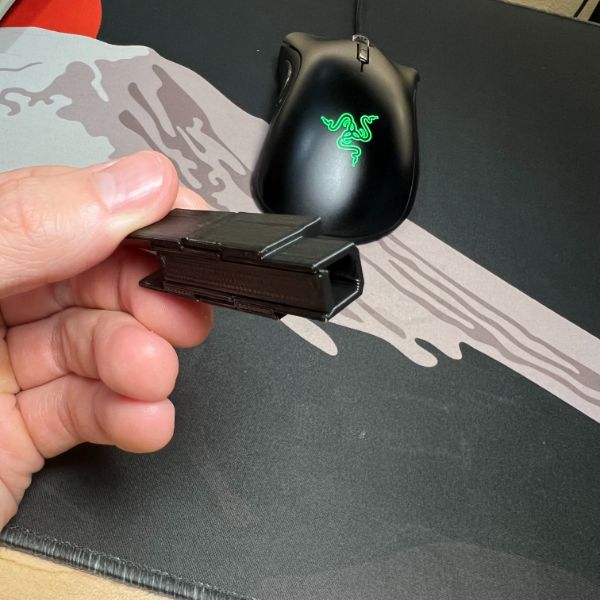
Square channels are liable to fail
Triangular maybe?
Need a Smart Dovetail mechanism for sliding a cover onto the back as well, since it’s liable to take on most of the hanging load, as people will want to hang on that rail
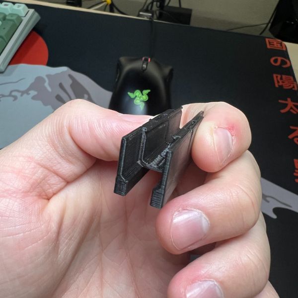
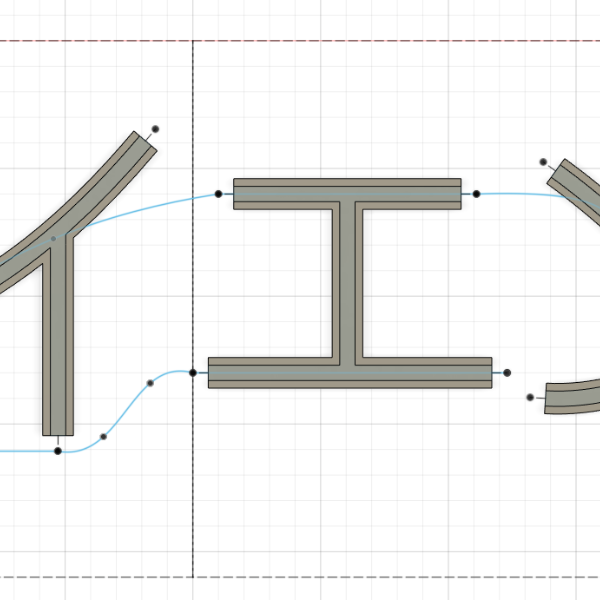
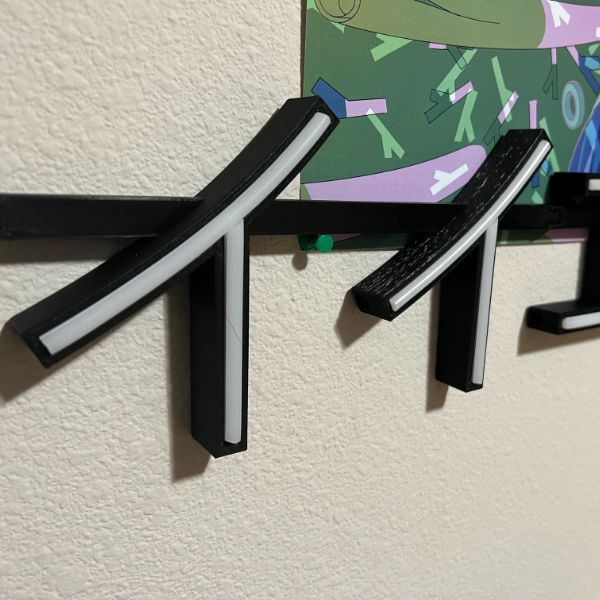
Need to add gap holes in channels that are locked in by other channels (like the H shape in IIEN)
the katakana n doesn’t seem to have flexing issues, which I was worried about
the 6mm channel/tunnel gap doesn’t seem to be an issue for the print overall, there’s just stringing in the adapter slots.
if I do a shallow dovetail that doesn’t extend to the edge of the tunnel, it’ll just produce warped lines in an area, there’s little chance anything will slide into there efficiently
Need names for some of these methods
Need an SOP for routing the support bars and minimizing them
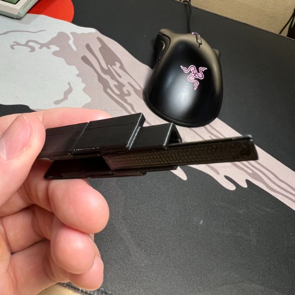
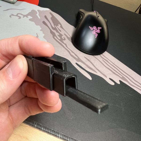
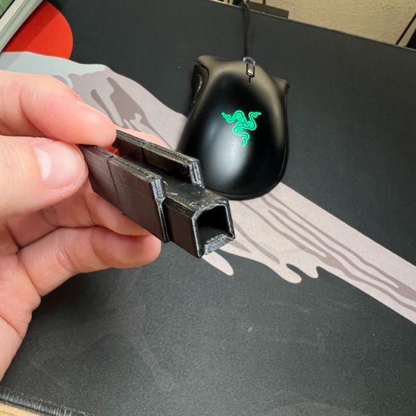
The 20mm height seems good to me
10mm wall height for upper section, 12mm width overall
10x12mm lower section with a 6x6mm square tunnel
6×6 can’t really fit 2 of the double wires
However, can easily fit 8 of the 22AWG if the doubling insulation is removed
Neon Flex Tests
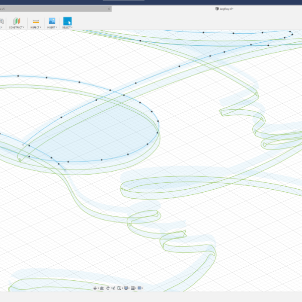
Modeling Procedure
Pick out SVG
Open New Model
Sketch 1: Max Size Frame
single construction rectangle 914mm x 610mm
Sketch 2: SVG
Insert SVG and resize to desired within bounds of 914×610
Sketch 3: Path
Use Splines to carve out the profile trace path over the SVG
If there is a curve that is sharply angled/crashes Profile Sweep,
Draw a separate spline that intersects at the angle point, and ensure there’s some overhand to trim off for later
End result should be a handful of splines that intersect with some spare to trim at every angled point
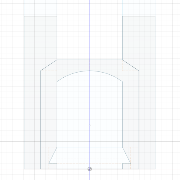
Sketch 4: Profile
Select each path and copy/paste the channel profile onto a unique Plane Along Path for each spline/unique path
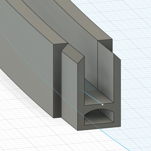
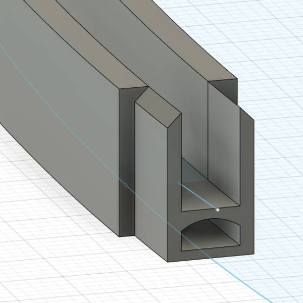
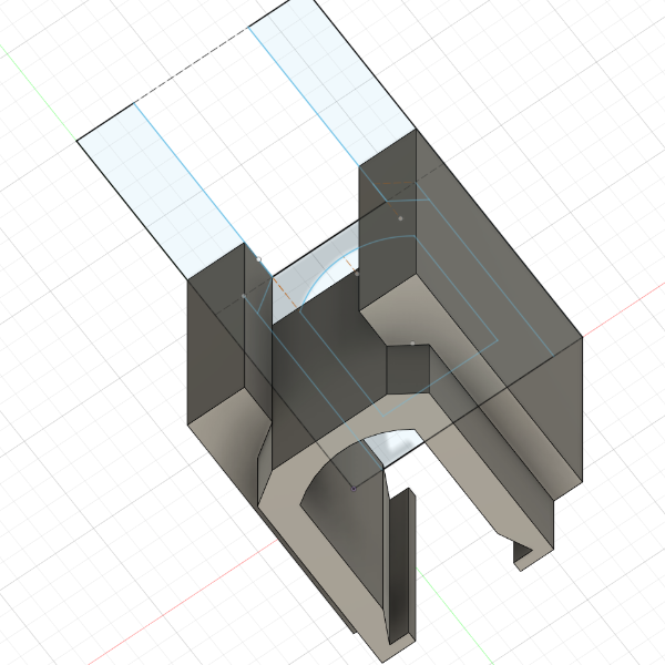
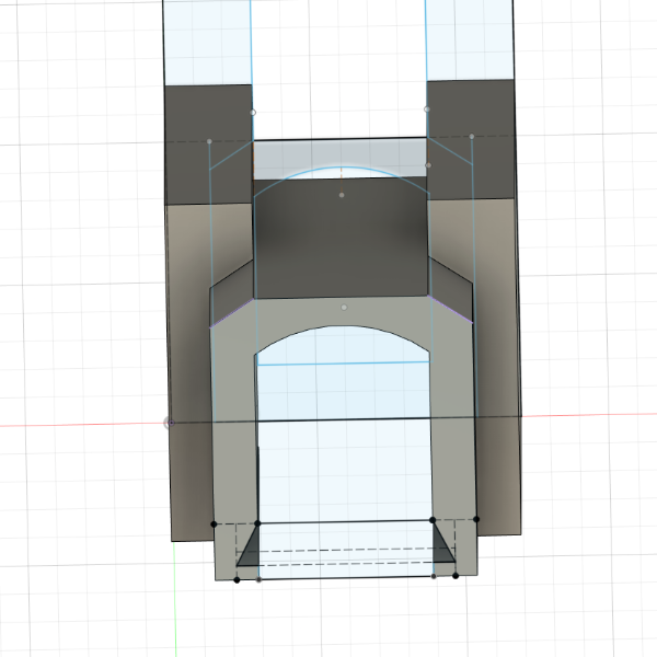
Profile size is 15mm x 12 mm with a 10mm x 6mm Channel and the rounded top tunnel underneath
The profile can be copy pasted
If it appears upside or something, just select the whole profile, move/copy, set pivot carefully, then orient properly
If it’s misaligned at all then the surfaces on top of the channel won’t join properly and the whole model will be tilted and it messes up the modeling
ALWAYS ADJUST PERSPECTIVE TO ENSURE YOURE SELECTING THE ORIGIN OF THE PATH CONSTRUCTED PLANE
Body 1: Sweeping Profile on Path
Sweep each Profile on each Path
Make sure to select Both the Channel frame and the Tunnel for the first sweep as the profile (2 Selected)
This means the tunnel underneath will be solid (this gets carved out later)
The first sweep on the first path will be a New Body
Every sweep after that should join into that main body as Join
Don’t let the sweeps form several distinct bodies, that also messes everything up later
Tip: You can adjust the splines of the path after sweeping to dynamically arrange the body
Body 2: Cleaning up Intersections
Once the complete body is made, there will be post-intersection channels going nowhere that need trimming off
Open a sketch on the top surface of the top of the channel walls, and carve out extra walls/extensions accordingly.
Line tool is usually enough for this
Reverse Extrude the regions to delete stuff.
10mm for blocking walls
20mm is sufficient (15 total) for extensions
If there are thin surface fragments, they can be deleted easily with a reverse extrusion of -0.1
ENSURE THERE ARE NO ADDITIONAL BODIES CREATED FROM THIN TRIMMINGS DURING THIS PROCESS
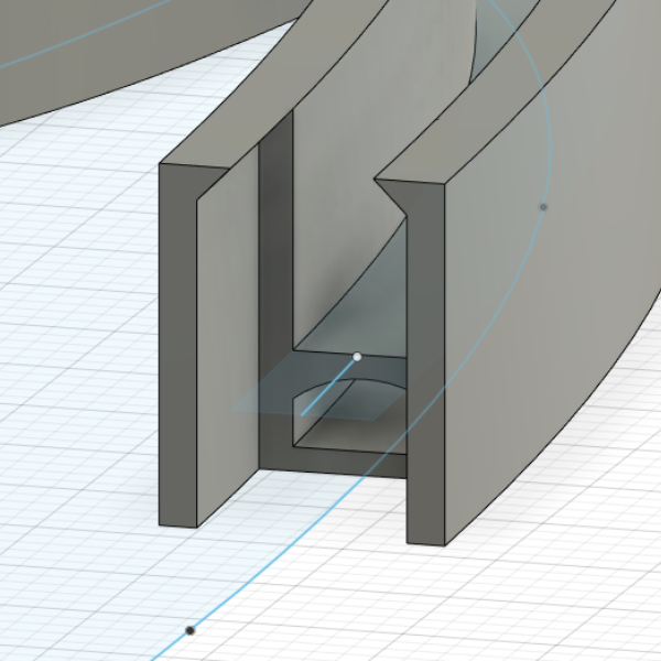
Body 3: Carving Tunnels
Once the body outline has been trimmed and pruned and decongested
Reference each profile and path again, and re-run a sweep, but this time with just the under tunnel’s profile, and as a cut
This cuts out the tunnel straight through both ends and appears after intersections, which cause the tunnel to get plugged if you don’t wait until after trimming intersected paths
Once all the tunnels are properly routed out of the bottom,
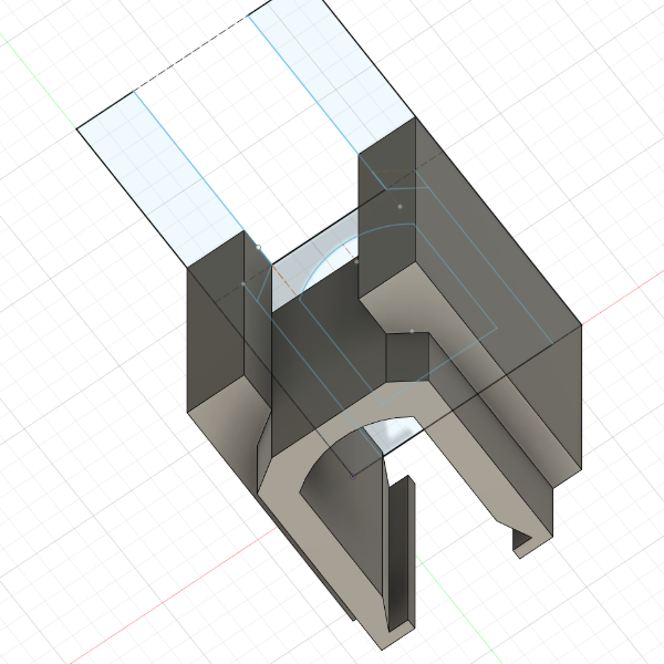
Body 4: Wire Holes
The Neon Flex can handle severe bends for the most part, but in a closed loop figure, there will be a point where the beginning and the end have to meet up
Pick a workable corner for a diagonal interface and carve out a simple square hole in the floor of the corner and reverse extrude to clear out the bottom.
This lets the wires leave through the side tunnel of the intersection
For intersections/jumps, might need to open the underside of the tunnel
One strip will run straight through, the other two strips will have to jump eachother from under, inside the tunnel.
This will require really short wires in really tight spaces and the process is liable to rip off solder pads…. we’ll get there when we get there
Might be able to use long wires and then tuck the excess into the extra tunnels on either side
Or might have to make the tunnel bigger overall
Or open the backside of the tunnel in general, which would be ugly but make it much easier
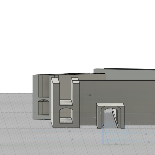
Assembly 1: Sectioning
Make a component copy of the finished total body
Rename it to base
Create a new sketch (CUT/ZONE SKETCH)
Overlay several construction rectangles of 250×210 over the part
Rotate as needed
Arrange them so there’s an overlap region of about 10mm per intersection
Make the intersections on relatively straight/consistent stretches of path
It’s okay and fine for the rectangle to be aligned with the compass and for the cross sectional cuts of the body to be slightly misaligned (we will be extending the adapter profile along the curve either way, so it’ll fit either way)
Pick which side is going to be male and which is female
Determine the number of parts, and clone the component that many times
BE SURE TO RENAME EACH COMPONENT AND EACH BODY OF EACH COMPONENT
This delinks them and lets them be edited separately
Assembly 2: Creating individual parts
For each part, simply overlay the cut/zone sketch over the full body, highlight all regions that are not the single part, and reverse extrude to delete them
Repeat until each part exists independently
Assembly 3: Creating Link Interfaces for Each Part
For each part, having decided previously which is male and female
Make sure the original PATH sketch is visible
Make an additional sketch along the top surface of the bottom of the channel
extend a straight line approximately along the curve of the PATH sketch, set it to 10mm. Ideally, fix the point directly onto the PATH curve
Leave the adapter length sketch and make a new sketch on the cross section surface for the adapter profile
2mm diagonal from the top at 45. that’s about it
Leave the sketch and prepare camera for sweep
Select the adapter profile for the profile, and select the PATH
Do NOT select the straight line length reference for the path
When sweeping, there will be two distance entries, since this is being done probably in the middle of a path.
The reverse distance will be going INTO the existing body for this PART of the whole body, and can be set to zero
The forward distance should be adjusted manually until it is in visual alignment with the distance marker
I don’t have a better way to do this, I can’t sweep exactly 10mm along a path yet, don’t know how to
for MALE adapters, go just short
for FEMALE adapters, go just over
This will prevent the male overfilling the female and creating a gap/space between segments
Repeat for all parts until all parts have the proper male/female link adapters
Production 1: Export
Select each COMPONENT referring to each PART and File>3D Print
Save the STL in a folder
Slice each STL in Prusa Slicer, adjust to get it to fit (according to the rotation of the rectangles on the CUT/ZONE Sketch)
Print each and make sure they fit together
END OF MODELING PROCESS
New Modeling Notes
Print Zoning
SVG Import
Path Drawing
Profile Set up
Profile Sweep Per body (join)
Trim
Profile Sweep (Cut)
Raising Boundary Walls (3.25mm thick, 5mm drop through)
Neon Sign SOP R1
To Do
Source 12V Adapters
Alibaba
Source Barrel Jacks
Amazon
Source Boxes
Amazon
Work on Pricing Structure
Shipping Cost: 42x36x6 box
UPS Ground
$42.08
42x36x6 Box
$6.90
~60′ Bubble Wrap
$6
Total
$54.98
Shipping Cost: 24x18x5 box
UPS Ground
$13.84
24x18x5 Box
$2.80
~15′ Bubble Wrap
$1.50
Total
$18.14
Materials Cost
Misc-Wiring
Solder
Heat Shrink
Cable
Superglue
$5
12V Adapter
$1
Neon Flex
$4.8/m
Filament
???
Barrel Jack
$0.44
Total
~$12
Labor Cost
Processing Order
Quoting Design
3D Modeling
3D Printing
Assembly
Shipping
Write SOP
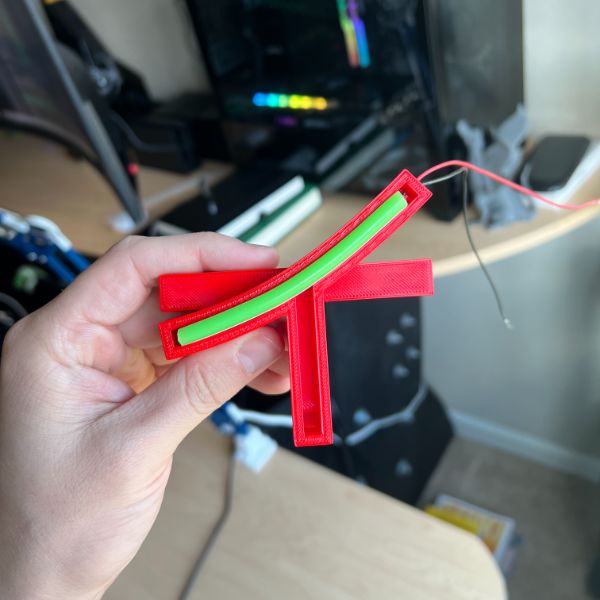
Design & Build Wolf
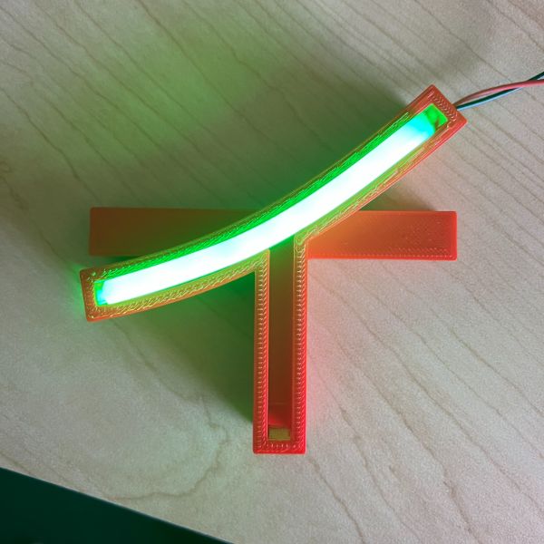
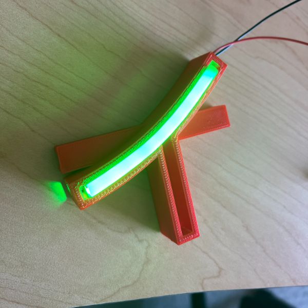
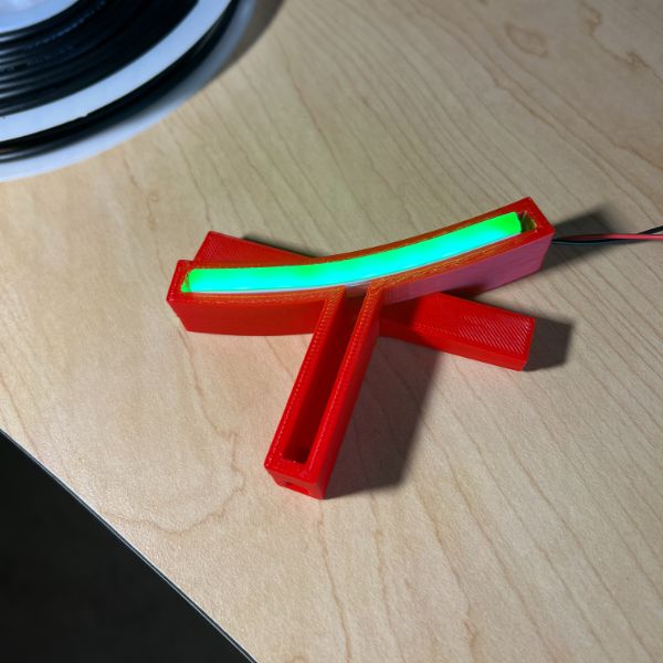
Put together Red/Green Demo for Etienne
Set up a Ledger for this Project
Research a Pi for Printer
Print Zoning
Paper Sizes
4A0
1682 × 2378 mm
66.2 × 93.6 in
2A0
1189 × 1682 mm
46.8 × 66.2 in
A0
841 × 1189 mm
33.1 × 46.8 in
A1
594 × 841 mm
23.4 × 33.1 in
A2
420 × 594 mm
16.5 × 23.4 in
A3+
329 × 483 mm
13 × 19 in
A4
210 × 297 mm
8.3 × 11.7 in
Paper Sizes
4A0
1682 × 2378 mm
66.2 × 93.6 in
$500
2A0
1189 × 1682 mm
46.8 × 66.2 in
$400
A0
841 × 1189 mm
33.1 × 46.8 in
$300
A1
594 × 841 mm
23.4 × 33.1 in
$250
A2
420 × 594 mm
16.5 × 23.4 in
$200
A3+
329 × 483 mm
13 × 19 in
$150
A4
210 × 297 mm
8.3 × 11.7 in
$100
Segment Ranges
0-5
5-10
10-20
20-30
30+
Total Length
0-100 cm
100-200 cm
200-300cm
300-400cm
400-500cm
500+cm
Segments
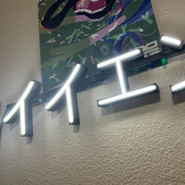
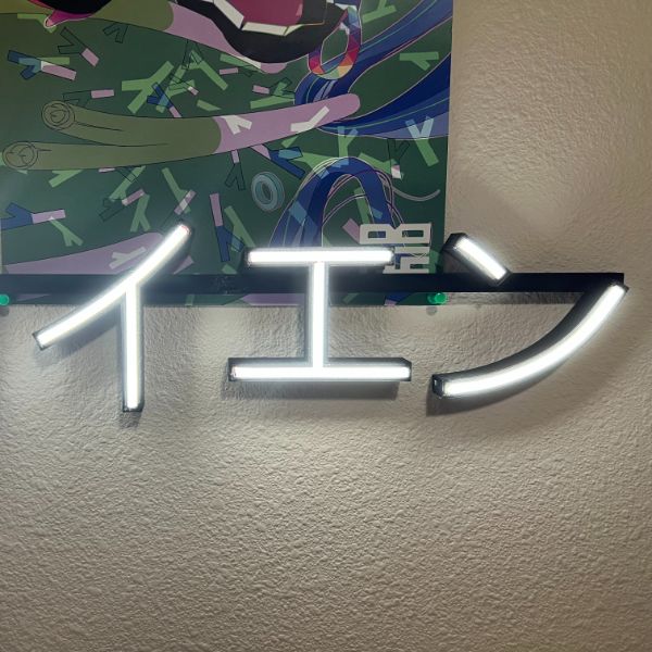
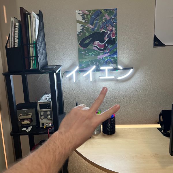
イイエン
9
AC Leaf
1
Heno
13
UNR Wolf+TKD
23
Total Dimension
イイエン
490 x 120 mm
19.3 x 4.7 in
A
AC Leaf
400 x 490 mm
15.7 x 19.3 in
A
Heno
UNR Wolf
1016 x 762 mm
40 x 30 in
F
Total Length
イイエン
84 cm
AC Leaf
220 cm
Heno
approx 230 cm at large size
910
200
200
150
220
120
200
200
100
UNR Wolf
Colors
イイエン
1
AC Leaf
1
Heno
1
UNR Wolf
1
Box Size List
A
24x18x5
2.07
B
24x24x5
3.47
610 x 610 mm
C
30x24x5
3.03
D
36x24x5
4.49
E
36x30x5
4.49
F
42x36x6
8.80
1066 x 914 mm
Discounts
Friends/First 10 Customers
-$50
Existing Design/Non-Custom
-$50
Cost Estimate
Design
Profile
Segments
Length
Price
S&H
Total
Discounts
Charge
UNR WOLF FLAG
32×58
813×1473
Channel size
Width
5.5mm
5.00mm under pressure
5.25mm?
Height
rounded shape on top of a rectangular extrusion
total height, unpressured, 12mm
rectangular section around 10mm
rounded around 2.0-2.5?
Summary
Try channel with bulb pushing out, so
10mm deep
3mm thick walls
5.25 mm wide channel
11.25mm wide total
13mm tall total, with 3mm bottom layer
strip run 100mm
base feature
100mm x 13mm x 11.25mm
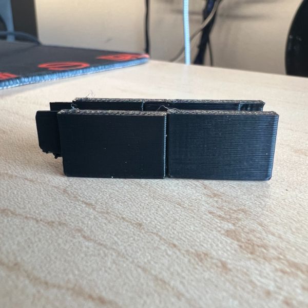
Results
First Print went great, just a straight line
Tried using B Line curves for a curved shape but it really didn’t work out very well
It seems like I can print these things pretty well if I’m clever about it
I just need to find a good toolchain for
Steps
Pick Image
Convert to Vector Format
Clean up and Decide on lines
Convert to 3D Object
Thicken Lines to 12mm
Steps
Try 6mm
Connecting Discrete Sections using 3D Printed Light Rails
Loss R1
results in 3 hours
trying a shallow transparent channel connecting the pieces both structurally and electrically
Connection Interface
It seems like if I can streamline this process enough it would be more worthwhile to print them…
To chase some shiny squirrels and speculate far future automation potential
A web portal that can take an SVG and generate the 6mm channel based lineart and give the user the option to check and see if it looks right before submitting to order
If people can order PCBs to the mfg drillbits and capabilities they can handle a 6mm SVG right?
it would be pretty involved to come up with an algorithm to determine the best method of wire routing for the whole system.
The neon doesn’t necessarily need to be strung together linearly by soldered wire connections. in theory the distinct segments could all return to a 12V bus line in parallel, rather than being connected serially
That would mean a lot more wiring in the back and it would probably come out pretty ugly
I haven’t cut the flex yet to see what it’s like inside
the other big hurdle I’m trying to get through right now is how to connect two linear pieces, and how to handle intersections
So I guess for today
Decide on Fit Mechanism
Dovetail?
seems too thin for a dovetail, walls are only 3mm
making them thicker would make the whole thing a fair bit bulkier and potentially uglier
would probably benefit from glue anyway
Already planning on gluing the neon flex into the channel
3D printing in general is going to be significantly more fragile than an acrylic sheet, which is an important consideration
I would probably have to find a packaging solution that the client could hold onto for transport.
It’d be self-defeating to give them a parts list and assembly instructions to snap together a 3D printed shape. Along with that, the tubes should be presoldered and managed. The client having to put them into the channels themselves is liable to break both the channels and the electrical connections. The whole thing needs to be assembled already on delivery
Or at least, for very large builds they could be in 2-4 major zoned areas…
Glue?
glue to flush surface is nothing but a recipe for disaster
Either a dovetail or a complementary hanging surface that can slot together
Even that would probably be more fragile than a dovetail though. Might be cleaner on the glue part though, not sure
Brace?
ugliest and weakest option
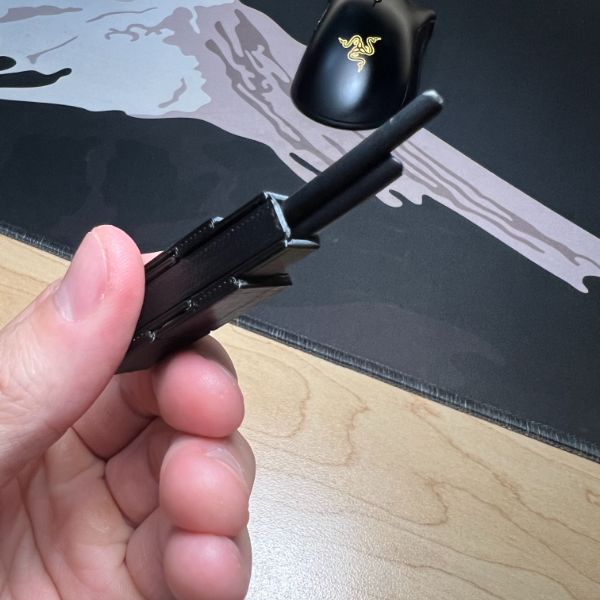
Linear Connection Test
Start with some 20mm rails at various thickness
3mm, 4mm, 5mm
Drafted up 3 different types of dovetails with various overhang levels, 1h print so I’ll have results soon
Dovetail V3, where it is open down to bottom and prevents any overhang, worked great, so I’m going with that
I’ll have to take some precautions when designing the prints
First, no intersections with connectors if possible,
Second, make connections on roughly straight paths if possible,
Third, include a reference print area in F360 so I can decide in advance how to chunk out the frame
Intersection Test
maybe i can circumvent the path collision issue by doing an additive path and then a subtractive, smaller path?
When using the sweep tool, a path and a profile are necessary.
Use the CONSTRUCT -> PLANE ALONG PATH
It’s very useful
For intersecting Sweeps, you can change it from New Body to Intersection and ONLY get the intersection area
I can also do a double sweep move where I run the first sweep on the intersected path
Then I run a sweep-CUT for the intersecting branch, this removes any overlap area and exposes in the middle fragments for me to reverse extrude/delete
Then I run a normal sweep on the same second path to recreate it. The downside here is that the intersection isn’t totally open and clear for both paths. One is blocked
this can be solved by using reverse extrude on the remaining walls, but its liable to be slightly off the line, especially if the intersection is between curved paths
Actually
Looks like the best approach is to Sweep 1 as New Body, then Sweep 2 as Join. That way its all one body. From there, Sketch on the surface and you can carve a surface out of all the intersecting area forms and then reverse extrude to delete
This should work for curves as well
Wiring
top is +12V
bottom is GND
obvious, but had to check
looks like 22AWG wire should cut it
source online says 7A limit
at 12W that’s a lot of power… but it’s only about 10W/m or 0.8A/m
I could splice a wire to the front of the strip but I risk losing the whole strip if I do that
Looks like I can run both 22AWG wires straight down through the bottom with a 4mm hole.
Thinking the 4mm is trashy and I’d rather just have a rectangular opening
Another issue is the fact that the wires will be exposed on the back. What will I do, hot glue them?
Maybe I can do a recession in the base of the channel that the wires can tuck into
Worried about them shorting together, hot glue might fix the issue.
Digging out the side wall and the floor of the insulation at the terminal point works fine, keeps the top clean and prevents exposing the guts to anyone looking at it. Should be fine as a best practice
Also allows some room for the glue to fill in too
Just need to make sure the separating cut itself is clean
Measured the most severe arc angle it can handle
It’s around 30 degrees between the three points of a sinewave (GND-PK-GND) measured from the angle formed at the PK
That’s at least with my current sketch for the channel
It could probably work with a thinner profile
A thinner profile does work, so I guess I’ll just have to work with what I’ve got for now.
I’m guessing I can’t make a thin wall variant or something like that because it seems like what breaks it is the overall width of the profile, which is going to need to remain AT LEAST >8mm (1+6+1) at all times.
Set up a wire tunnel in the floor at the cost of 1mm extra padding on the floor
needs to be an arc tunnel so overhang effects don’t choke the tunnel
and a circle seems wasteful when I could just have a square gap for the wires as well
Leaving room for the outline the print area usable is 240×210
Process for harsh turns, angles, right angles
Have two distinct paths
You can copy paste the profile on a new path-plane to save time, which is AWESOME
Have the two distinct paths intersect and overshoot past the point
Sweep both, and have the second one join in
Crop off the rest using reverse extrude
For thin strips, reverse extrude -0.1
devised a method of overlaying construction rectangles as rigging to lay out how the piece will get chopped up
a huge issue though is that it HAS to get cut along an axis perfectly perpendicular to the channel at that point,
the dovetail extrusion will be misaligned otherwise and useless
Fixing the blocked wire channel in intersection issue
Trying a curved intersection where the channel is modeled on the profile, but i use it positively for the first sweep, clean up the intersection, and then run just the channel negatively for the second sweep
Figured out how to SET PIVOT while moving around a copied sketch to orient it properly
Next is figuring out how to handle sharp angle splice wiring
Three types of intersections, basically:
2 point – sharp angle
3 point
4 point – full intersection
methods
chain: at an intersection, use short wire to jump from one pad to the next to keep it going
Still need the insulation cut at a sharp angle, but can be exposed underneath to a decent extent
leap: at a full intersection, have 2 paths continuous with one strip, have the other two snake under in the tunnel to connect to eachother
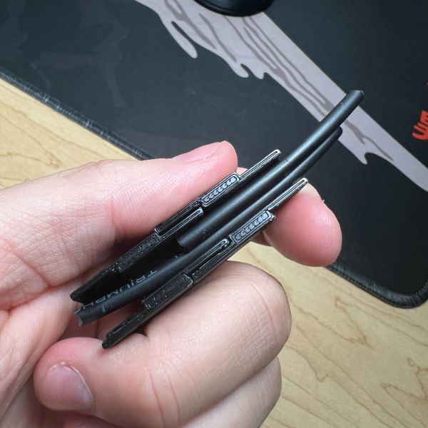
It doesn’t look like i can cut around the directionality of the strip
since the PCB is flush to one side, i can only meaningfully diagonal cut it to taper off towards the PCB
Other option is to cut ahead of the black line and give myself room to taper back
But then the PCB would be recessed
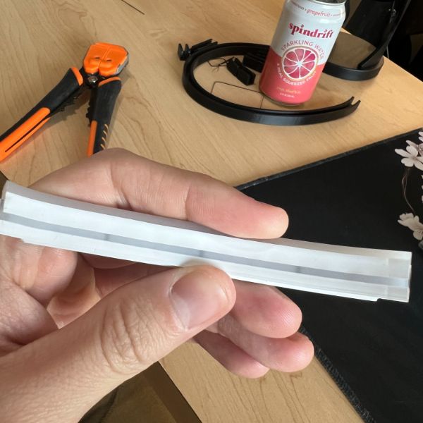
The Neon flex is very flexible and can bend back on itself pretty severely.
I’m guessing for harsh angle 2-intersections (passthrough) i don’t even need to splice
The only time I’ll need to splice in that case is to separate the beginning and end of the line. They’ll be physically flush but represent opposite ends of the strip.
Then the power can go out the side of the channel
The diagonal cut makes a knife edge shape
The PCB is on the longer side, the knife’s point
the shorter side is non PCB
The black dots indicating the cut line are always on the PCB side
and
The long side of the knife/the knife point needs to be on the outer wall of the angle, regardless of the angle
therefore, the PCB/Black Dot Side should always be facing OUTWARDS from the shape/angle
BLACK DOTS OUT!
Procedure for getting good, matching cuts
Determine the interfacing plane between the two strips
Ideally, put both strips with flush flat cuts in towards the joint
Then, Align the blade, and make shallow parallel scoring strokes atop the insulation
Either by aligning the blade in the gap in the middle, then moving it over to the strip
or by pushing one strip into the interfacing plane and scoring it directly in line, then switching to the other strip
Second is probably more consistent
Either way, make sure they’re parallel and in alignment with the angle
There’s no real need to carve out a right angle of insulation so that the flex can fold into more severe angles, it’s flexible enough to force that naturally
Also, that technique only works one way either way so
.00
Mounting Methods
Command Strips
Tacks, free hang
Thumbtack Zones?
Wire is ugly
Dimmer?
Start/End Splicing Procedure
Do not cut flush, cut slightly ahead of the black dot to get the entire solder pad exposed, with the light still embedded in the insulation fully
have short wires running into the solder pad/insulation sheath. The sheath should provide some stability and hold it.
if the wires are too long they’ll tap 12V across the LED and blow it out. This can create huge issues for production as a strip cut to length and then one short is completely useless
Once the wires are on, run them into the channel, make sure they’re side by side, they can’t slide through if they’re on top of one another
Run the wires out of the side channel so the print can remain flush to a wall
they slide through best through a circular pull, rather than a linear one
Once the led strip is in and the wires routed, plug it in and make sure it still works/the solder pads haven’t snapped off
Run the other end of the strip up to the junction point
Press them together to check the fit
pull the nonwired one out a bit, then quickly add glue, and press them together
hold them together flush until the glue that spills through the top cools off enough to peel off
use IPA to clean up sparingly and accordingly (find a better adhesive)
wire up and plug in
New Software
Guys at the makerspace told me there’s a free personal use license that requires annual renewal for Fusion360 and I don’t have to use FreeCAD, nice.
Was also recommended Inkscape
Looks like .svg is the vector graphics file and Inkscape is the tool for that
Then I upload svg to Fusion?
Inkscape
Inkscape Tutorials
https://www.youtube.com/playlist?list=PLqazFFzUAPc5lOQwDoZ4Dw2YSXtO7lWNv
Fusion360
Playlists
Fusion 360 for 3D Printing
https://www.youtube.com/playlist?list=PLrZ2zKOtC_-Bl4uHmsx5pZVUpJKFif3lR
Learn Autodesk Fusion 360 in 30 Days for Complete Beginners!
https://www.youtube.com/playlist?list=PLrZ2zKOtC_-DR2ZkMaK3YthYLErPxCnT-
License
Fusion 360 for Personal Use
https://productdesignonline.com/tips-and-tricks/how-to-get-fusion-360-for-free/#personal
This new personal license is intended for Hobbyists users, for non-commercial use only.
You’ll continue to have access to everything you need to complete those personal projects. Including all the design, engineering, documentation (2D drawings), and manufacturing capabilities included in a current Fusion 360 Commercial subscription. Some features are not included, as outlined below.
Personal Use Qualifications
Individuals with non-commercial personal design projects.
Individuals doing home-based non-commercial manufacturing and fabrication.
Using for personal projects outside of their primary employment.
Engaged in Hobby Businesses making less than $1,000 a year.
Learning for personal use, outside of a company environment or commercial training.
Creating YouTube videos, blogs or other web-based content.
What’s NOT Included in Personal Use
Access to collaboration – you won’t be able to invite people to work on projects or the same file. Instead, you’ll have to share the public link or export
Export files to your computer. Opens the Export dialog box and allows you to choose a name, file type, and location to save the file to.
your file, where the other user will then have to import the file into their own data panel
Opening The Data Panel gives you access to your Project Files and Folders. Click the Show Data Panel button in the upper left of the Fusion window. The Panel will expand on the left side and display the project folders. You can also add members to projects and Import data from other sources.
.
Data management – some of the data management capabilities will be limited. However, you will still have access to the regular data panel and F360 hub, where you can organize your files.
Software translators – the ability to import NX, Catia, Solidworks, Creo, and Inventor files are not supported.
Generative design – generative design is only available to commercial subscribers due to its resource-intensive cloud need.
Advanced simulation – you can run some basic simulations locally; however, the advanced simulations that require cloud credits are only available to commercial users.
Where to Get Support – Personal Use
Community forum – Support for this subscription type is provided through the Fusion 360 community forums.
Product Design Online – Of course, you can also learn a lot right here or via my YouTube channel.
Registering for the Personal Use License
Go to the Fusion 360 for Personal Use home page.
Select
The selection mode controls how objects are select when you drag in the canvas.
the orange “Getting Started” button.
Select “Sign In” at the bottom of the page.
Sign in to your Autodesk Account. If you don’t have an Autodesk Account, select the “Create Now” button.
Once signed in, click the “Get Started” link.
Note: If you were already using the Startup/Hobbyists license the link will automatically assign your account to the new personal use subscription.
The download of Fusion 360 should then automatically start. If you already have Fusion 360 installed then you can cancel/delete the download – there is no need to reinstall it!
Note: There may be up to a 30-minute delay before the new subscription is visible in your existing installation.
View the step-by-step video instructions on how to download and install Fusion 360 for personal use.
Fusion 360 is the first and only integrated cloud CAD, CAM, CAE, and PCB software platform of its kind
Unify design, engineering, electronics, and manufacturing with Fusion 360
Crazy ass description
Tutorials
Fusion 360 Tutorial for Absolute Beginners (2020)
https://youtu.be/qvrHuaHhqHI
Making a stamp this video
Make a unique component for each part of the design
sounds like components are like bodies
Under ASSEMBLE -> NEW COMPONENT
Not sure what internal/external means
After making a component, press L to select which plane to sketch on
Select the plane and enter sketch
L to sketch lines, enter lengths and angles, tab between them, etc.
After creating an enclosed shape, extrude it
go to SOLID tab > CREATE Section dropdown > EXTRUDE
Note revolve, sweep, loft, etc.
After Extruding, Insert SVG
SOLID tab > INSERT dropdown > Insert SVG
Select planar surface to insert SVG
Note, InkScape saves as SVG by default
Fusion inserts the SVG as a new sketch
Need to select every enclosed 2D and extrude manually as such
Take note of nesting when creating a new component
If an existing component is active when a new component is made, it will by default nest under the original component.
Just drag and drop onto the root filename to denest it
For the second component, the handle to the stamp
Create the new component, then define the start plane by using CONSTRUCTION
CONSTRUCT has a tool called MIDPLANE where you select 2 Planes and it defines your basis plane as the center plane between the two
Once the plane is determined, the geometry of the prior object can be projected onto the midplane sketch using P for PROJECT
select the enclosed shape and OK the project command and the lines will be purple to indicate the shape is derivative of another
When projecting, you have to pick the plane first and the shape second
Clicking OK is necessary in this pack
Under the SKETCH tab, there’s an offset that allows you to expand the geometry
0.25mm works well for sliding 3D Printer joints
You can also offset in both directions
You can add lines to the sketch to carve up the body and it will automatically recognize it as distinct bodies. and lines auto snap too. This is much more straightforward than FreeCAD
While sketching, to activate construction mode, you have to click Construction under Linetype in the menu on the right for SKETCH PALETTE
Construction is not written its just an icon
C is for CIRCLE not for construction
You have to click it to manually toggle it
If you need to draw in free space you can use CONSTRUCT -> OFFSET PLANE
Select an existing plane and then create a new sketch plane offset from it by some distance
Loft tunnels between two shapes
so two circles of different sizes some distance apart on parallel planes can be lofted to create a tapered shaft between them
Once the model is finished, save, and Right click root filename and hit ACTIVATE
that enables all component bodies at once and makes it good for show
From there, File, Export for 3D Printing for the STL
Notes
It looks like the process so far is
Get handwriting in SVG format from InkScape
Import SVG into Fusion 360
Extrude upwards
Take edgepoint of extruded brushstroke and create a new plane
Form the 12×12, 6mm channel cross sectional profile
Use Fit Splines to carve out a curved trace
Fit Splines can’t intersect eachother and so they can’t be too extremely curved or cross over
Not sure how to get around this other than making many components and then joining them
Running print for now on Angel’s big R and seeing where I can go from there