
11/7/2022 – 11/20/2022
Summary: Dialed in the neon signs. Started taking orders. Looking into building rockets again. Cleaned up Lab. One year consistent posting as of W.
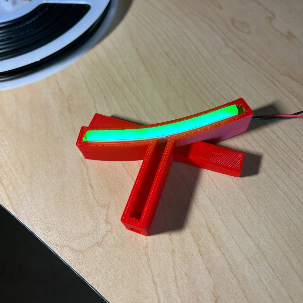
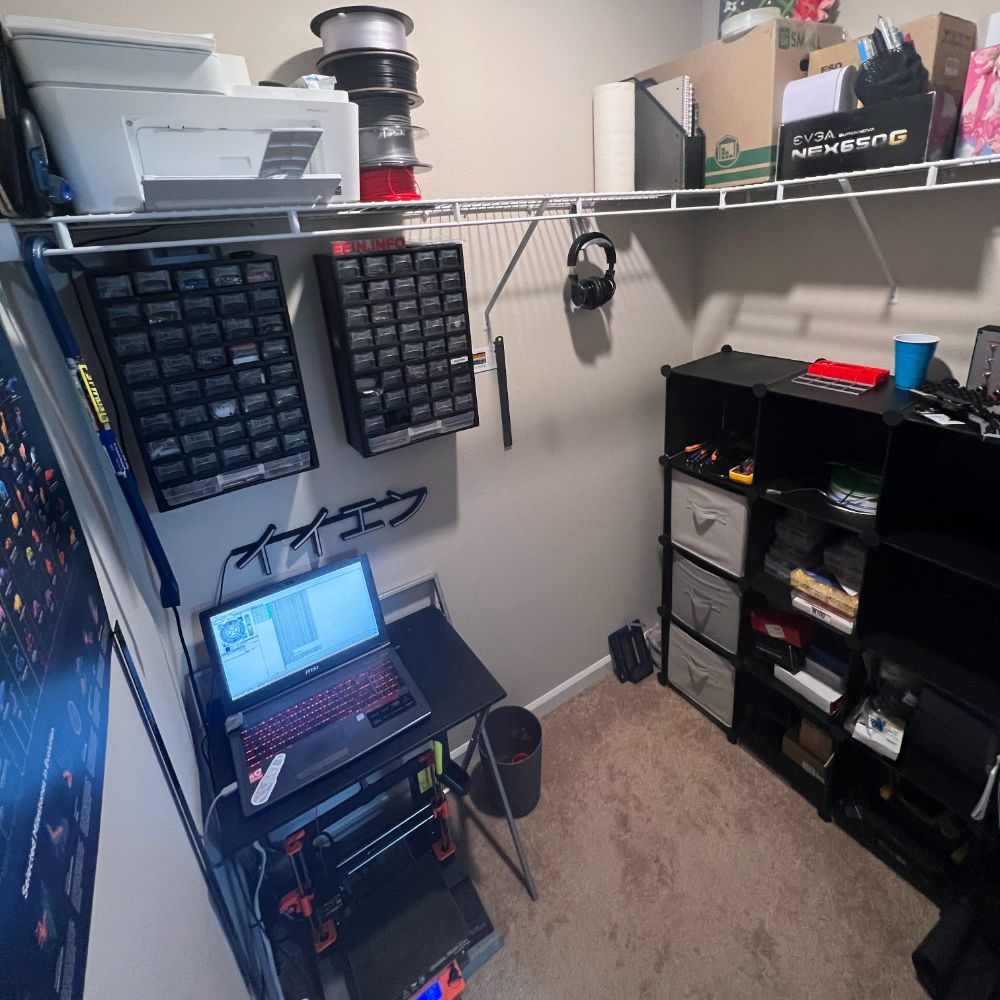
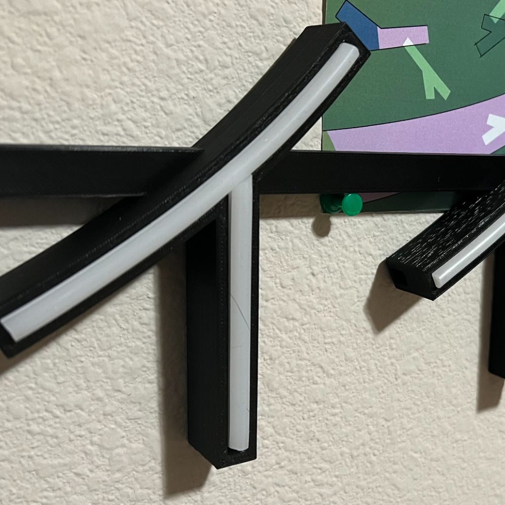
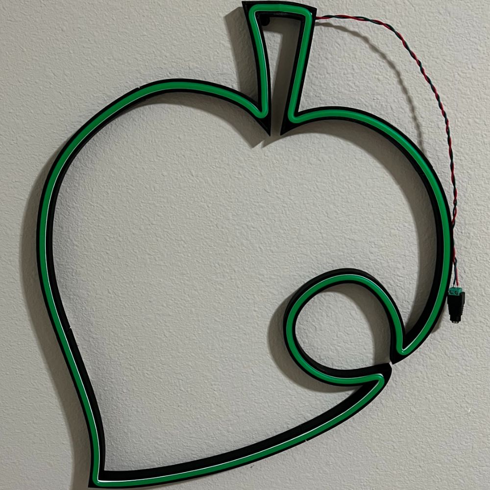
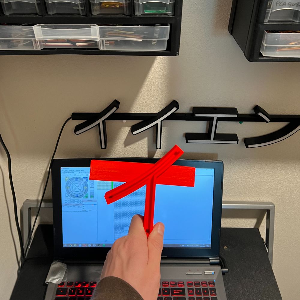
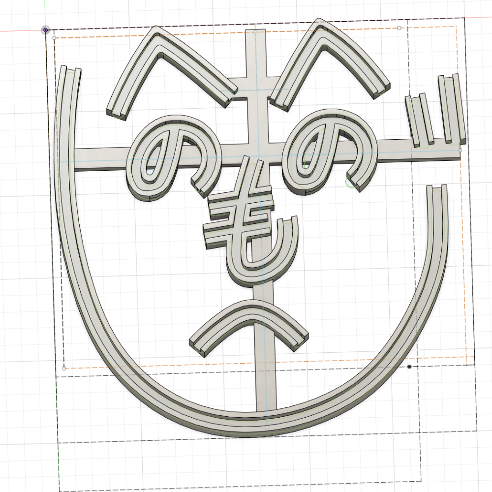
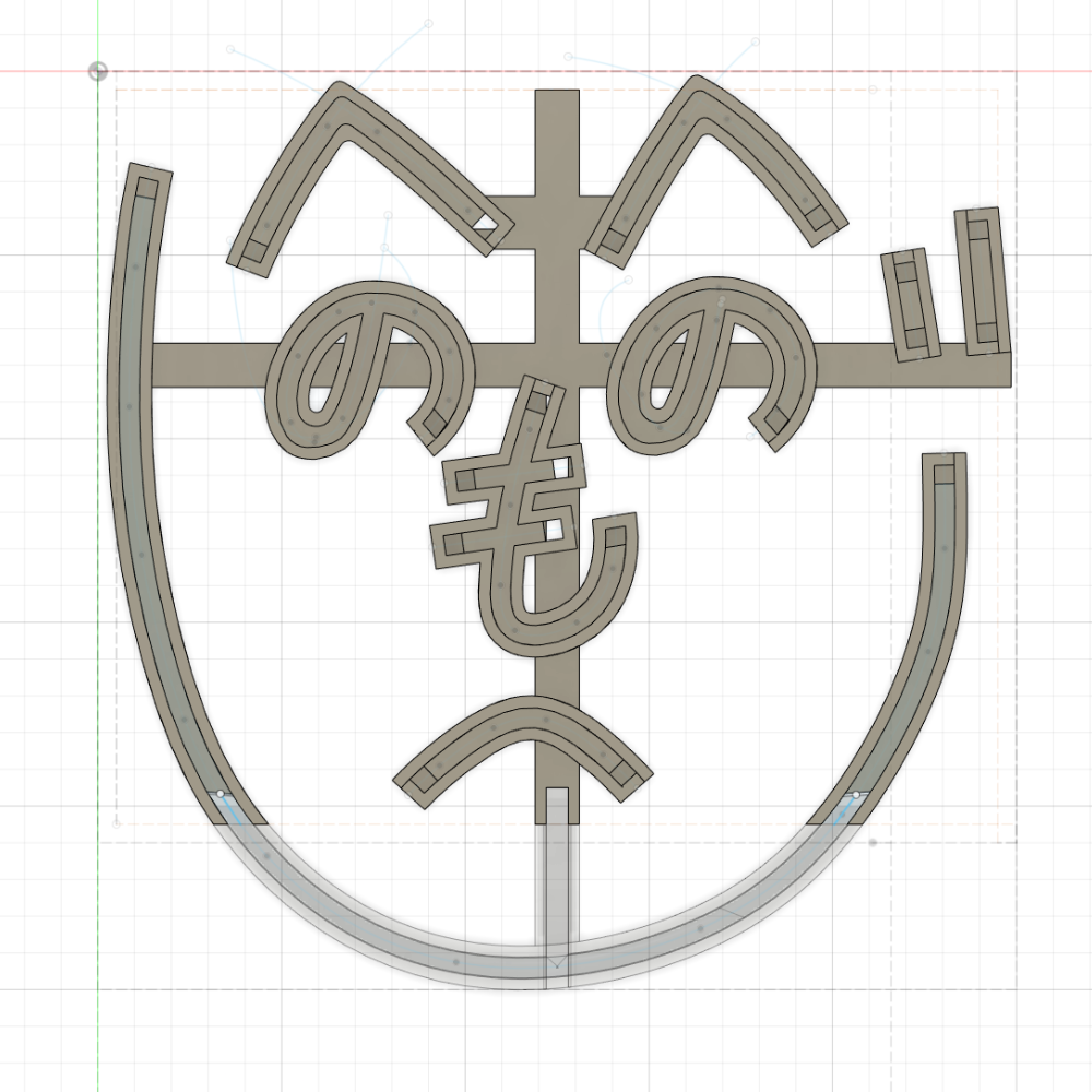
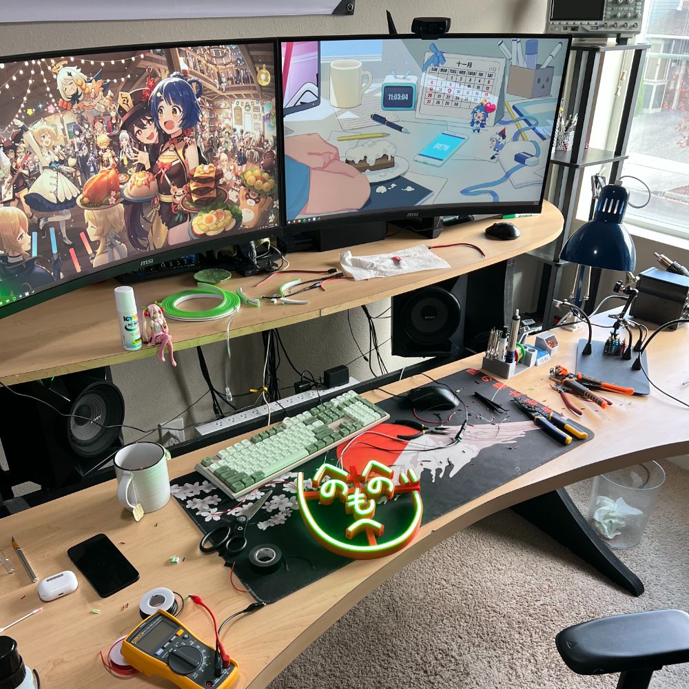
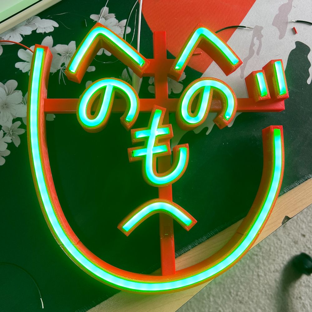
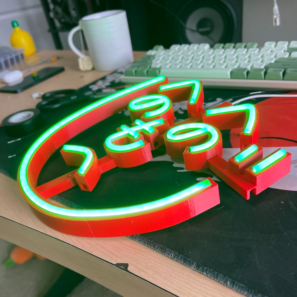
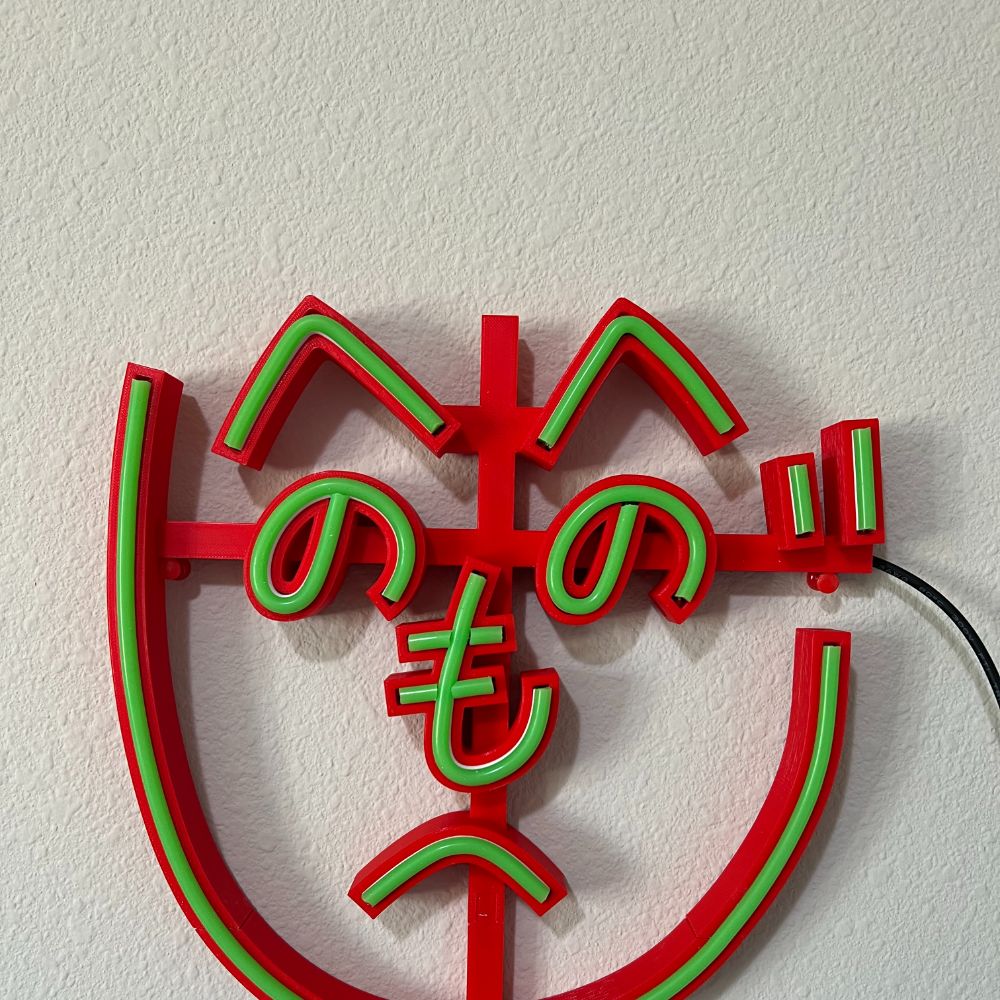
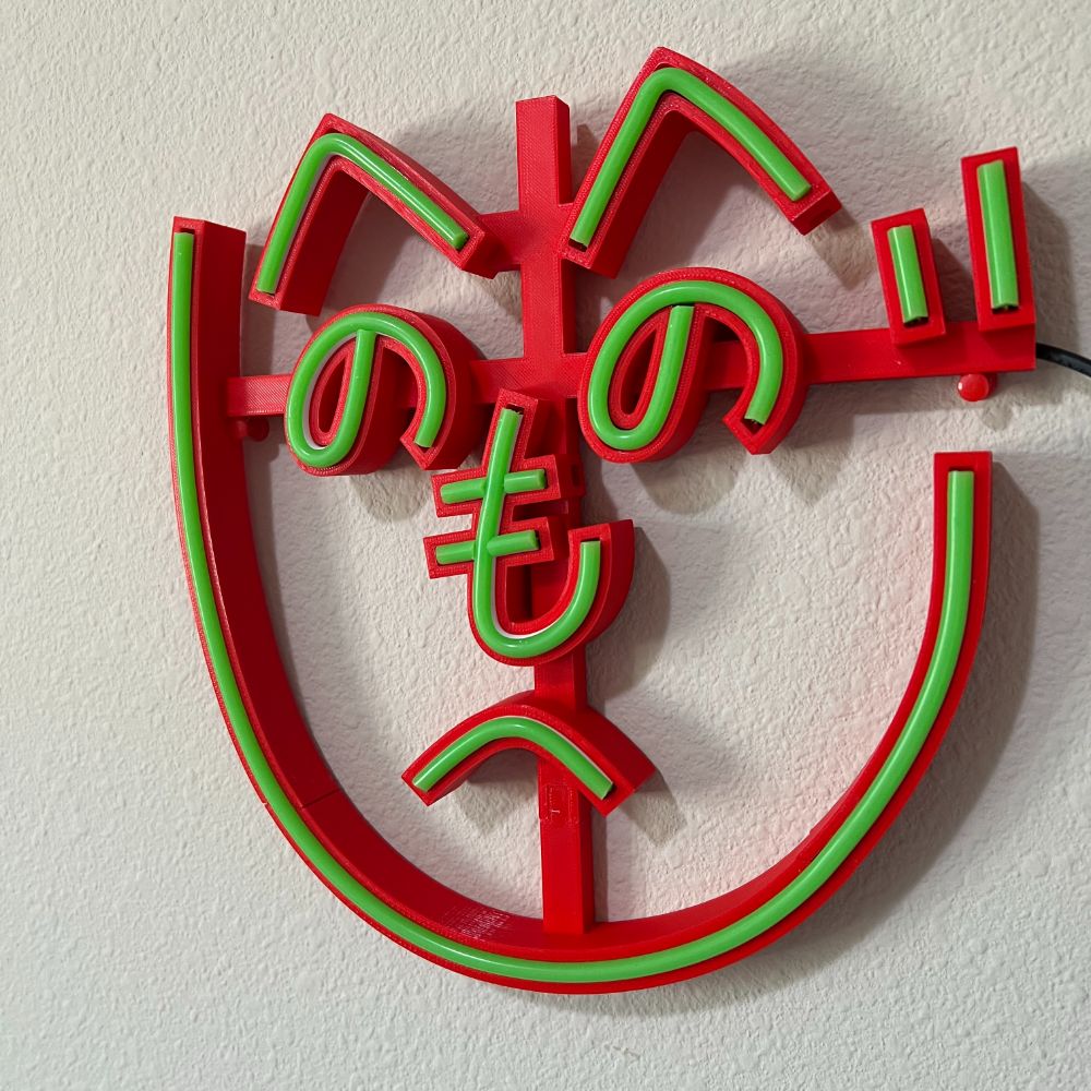
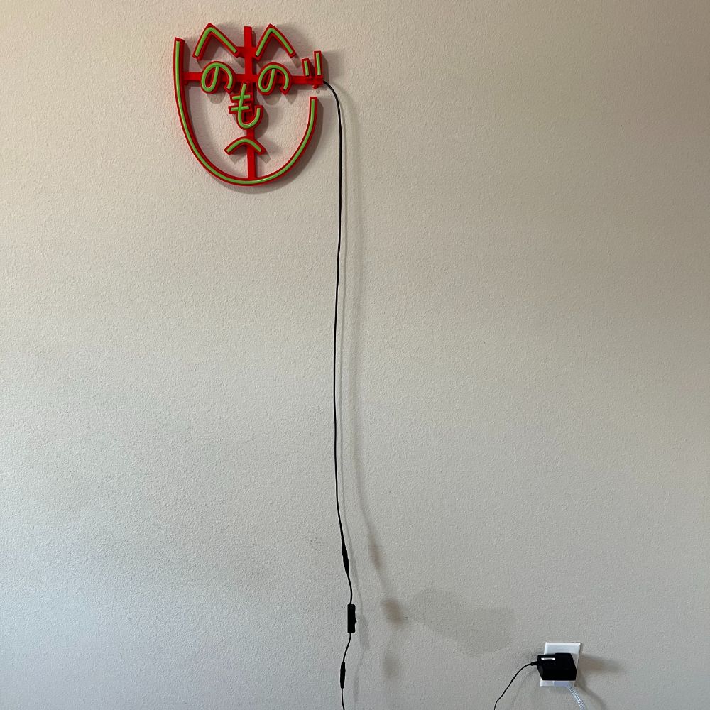
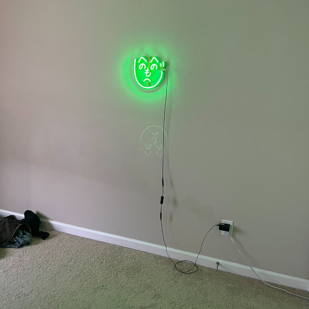
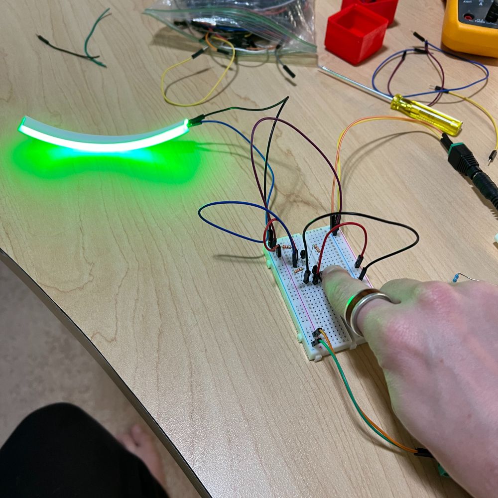
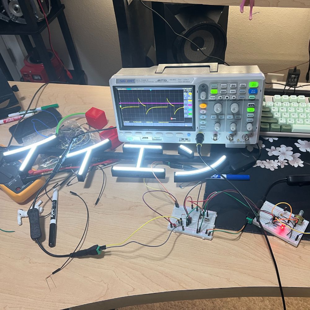
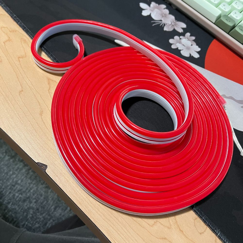
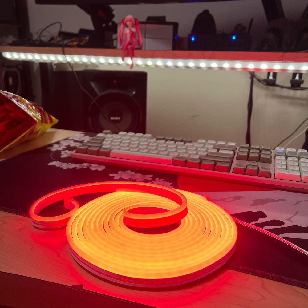
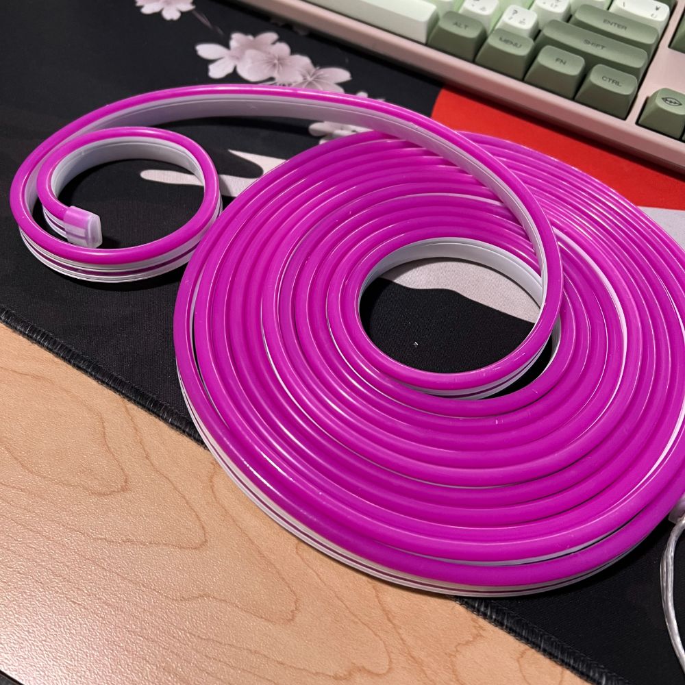
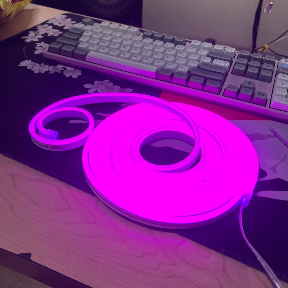
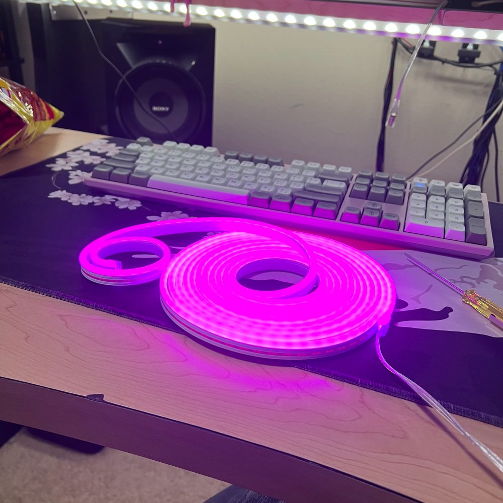
Tidied up the lab and organized some stuff. Really drilled in and got the process for modeling these neon sign channels down. They’re coming out really clean now. Made a flyer to sell them to family and friends to build a portfolio of completed works so I have photos to put on an etsy store. Got about $1500 in orders in the first two weeks, which is promising. But now I have a bunch of work to do.
Played with the idea on and off for the last two weeks of setting a long term goal of building a rocket that can land upright per BPS.Space. Also extending that idea to building a spaceshot rocket, and wondering if we live in a world where a one-man moonshot is possible. Learning about rocket engines and such now. It’s a good gelling factor since it lets me pursue chemical/pyro stuff, metalworking/manufacturing stuff, and electronic/control stuff all at the same time.
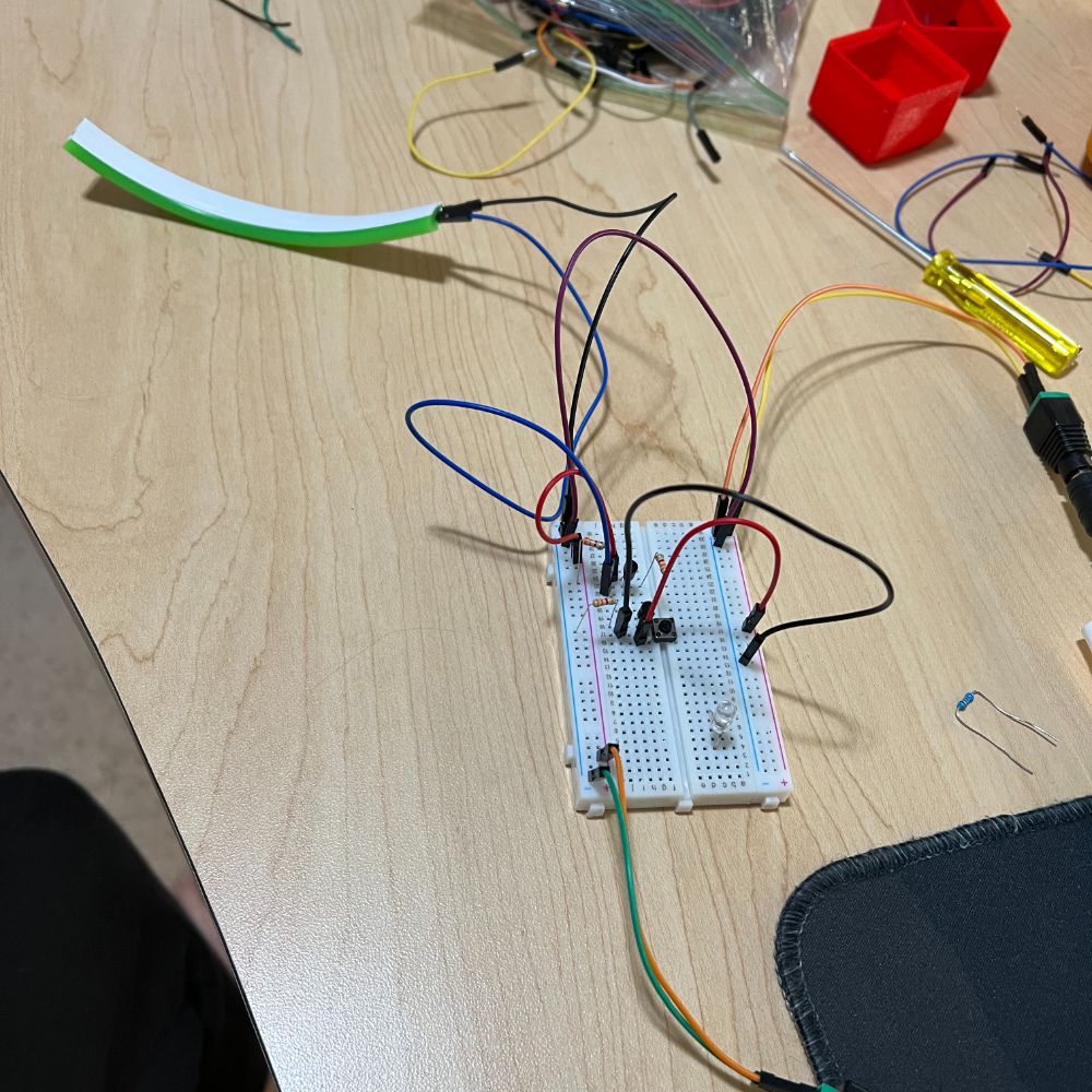
Also briefly messed with my PWM motor control board PCA9685 or whatever it is. Also got to use the knowledge from AoE Ch2 to design a blinker circuit for a sign order.
For now the plan is to continue Aoe, Rocket Research, and grinding out these signs. Discounting labor time, I’m at a financial breakeven point for all the materials I bought already, which is nice. Not sure how scalable this whole endeavor is though.
W is the first sprint I did last year after building my new computer and it’s nice to see how far the lab has come since I committed to the biweekly updates for 2022. Looking forward to what happens in 2023. Upping picture size to 1000×1000 from now on instead of 600×600.


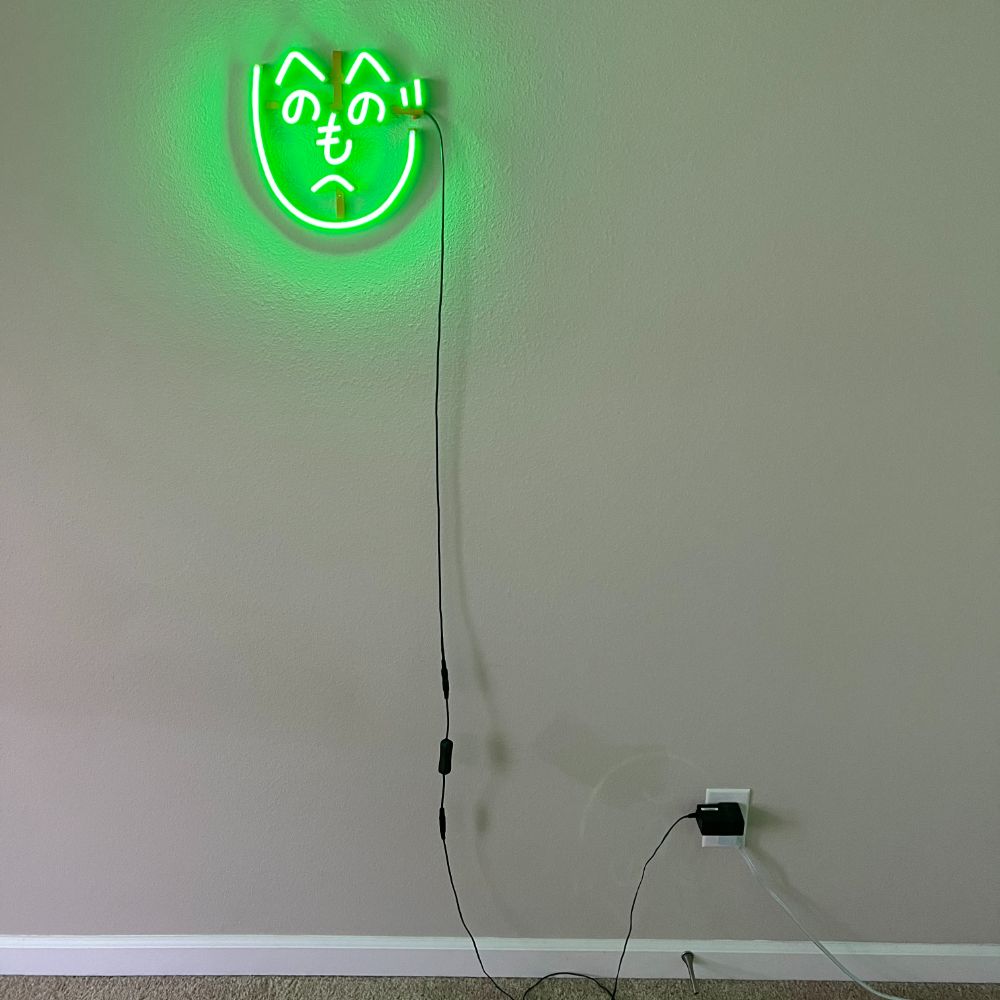


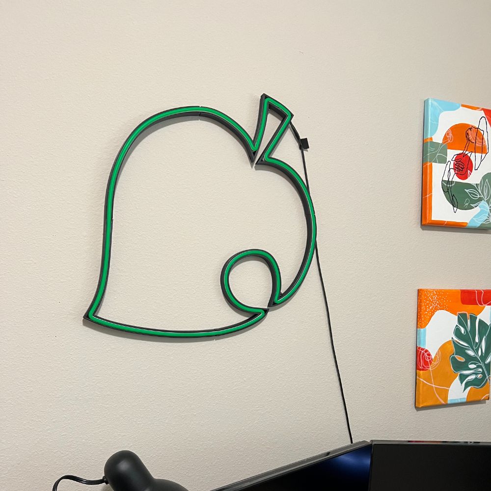
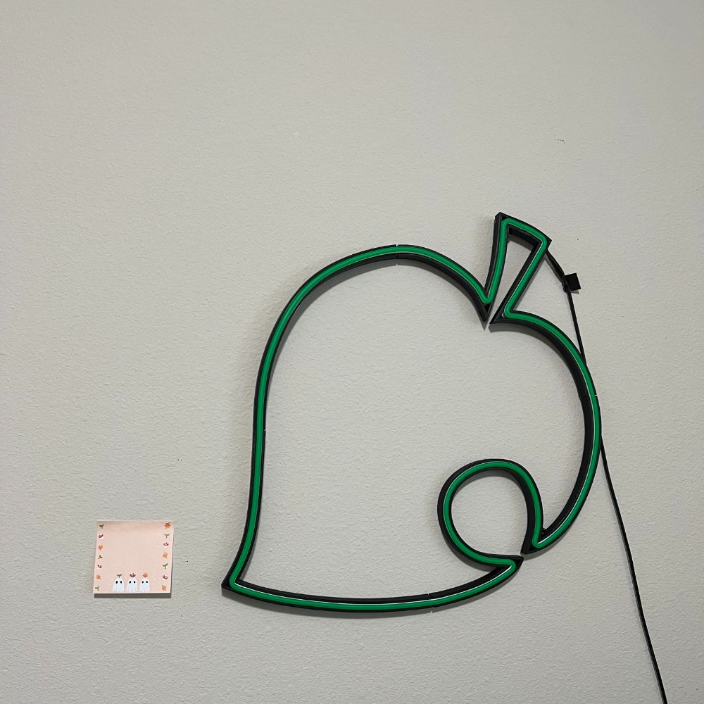


Walrus
PROJECT 天気団 – Weather Corps
Init
Objectives
Let’s Chart this out
First, assumptions
It took BPS.Space 7 years with no engineering background to land a rocket upright like SpaceX.
I believe that I could manage the same, in a shorter period of time.
I also believe that, if I can land a rocket upright, I may also be capable of a spaceshot rocket, as USC’s undergrad team managed this 3 years ago. This would be significantly higher profile and more expensive
I also believe that, if I can make a spaceshot rocket, the extension to making a rocket that can reach the moon is a similar jump in complexity
One issue is, will the rocket perform a science or logistical mission regarding the moon, or will it simply crash into it, as a missile?
“we’ll clean it up later”
With this long timeline. It’s easy to get overwhelmed and think about the moonshot too much. Focus on what’s in front of you
Timeline
Stage 0
Research
Stage 1
Landing Rocket
Stage 2
Spaceshot Rocket
Stage 3
Moonshot Rocket
The purpose of this whole mission is NOT for the moonshot rocket to make money.
It is to centralize my efforts and draw up my potential talent and actualize it as aggressively and as clearly as possible.
In that sense, this is less of a commercial endeavor and more of an athletic one. It’s a training boot camp or an apprenticeship with a Masterwork at the end.
Similar to “would you rather get rich quick, or get rich for sure, at the end of 5 years?” but with “being a world-class engineer”
This comes from my personal drive to be among the best in the world at what I do
The Rocket is something that excites me that I’ve had a long-term source of passion in, and it’s also loud enough that the process of me making it can also develop a media platform. The purpose of the media platform is 3-fold
1. to help me get easier access to the people I want to affiliate with
2. educational, so i can help other people learn what i’ve learned
3. to give me social leverage for future projects
The purpose of setting out to build a solo moonshot is
1. to drive me towards an extremely challenging/ordering long term goal
2. to accelerate my development as a master/world-class engineer
3. to set out to do something nobody has done before
4. to qualify myself publicly as a world-class engineer and alter my career path
5. to create a platform of inspiration and education for others
who not how is not relevant here because this is a competitive/athletic endeavor
the future rockets may need funding due to size and complexity, which i can produce on my own in other ways. not something to worry about right now.
As it stands, I don’t have a leg to stand on, my skills are inferior and I don’t even deserve to be in the room for a conversation about building a rocket that can land itself upright.
Thus a year or two of eating the shit and studying hard while stacking cash in the meantime is in order
As I start the long night of studying – it’s good to clarify the intent and purpose of the mission so I don’t get distracted.
There is a MEDIA aspect to this
documentary of process
engineering content
educational content
social content
There is a TECHNICAL EXPERTISE aspect to this
me understanding 150% of anything I present is a prerequisite
It is not enough to simply build the rocket and know that it works
I have to know how it works down to the fibers and be able to explain it
There is a FINANCIAL/LOGISTICAL aspect to this
Time & Money
This isn’t about making something happen or changing the world or making money
It’s about making something out of myself.
So build a side-business and make some money
Wake up early if you want another man’s land.
Sharks are the apex because they will follow their prey for thousands of miles
Start saying NO. To everything. And Execute.
For a progress vlog. either not relevant while I’m reading the book (what’s the point?) – or not important to bells and whistles right now
buge does just fine not giving a fuck how his video production quality is. not relevant. next topic
execute.
Bodies of Info – Priority Order
Art of Electronics
C Programming
Automate with Python
Metalworking Shop from Scratch
[Rocket Textbook Recs from BPS]
Kerbal Space Program
Book of Maker Skills
Universe Review
Hyperphysics
Feynman Physics Boxset
Road to Reality
Scratch
BASIC QUESTIONS
What is the minimum spec of a rocket capable of reaching space?
looks like heightwise answers range from 13 – 30 ft
if moonshot, probably on the higher end
NOTES
Rocket engine cycles: How do you power a rocket engine?
https://youtu.be/Owji-ukVt9M
Cold Gas Monopropellant
High pressure gas tank
spits cold gas out the engine, no combustion
gas expands in the engine, gets colder
output thrust flame is icy
COPV – composite over pressure vessel
just take a metal tank and wrap it tightly in carbonfiber/kevlar
pressure in the tank must be higher than the pressure in the engine or it backflows
bad
if you open the valve too much the sudden drop in pressure causes a huge temperature drop which can condense the gas into a liquid
simple, reliable, but limited in raw power. somewhat inefficient
one moving part – valve
good for tiny nitrogen cold gas maneuvering thrusters
used on smallsats and astronaut jetpacks
Pressure Fed Engine
monoprop
two tanks in series before engine
deepest tank is pressurant tank, high pressure
modulated valve flow into the propellant tank, chemical reaction occurs
two exits – 1 backflow into the HP pressurant tank, not gonna happen
other exit is the engine
as long as the propellant tank remains higher pressure than the engine, no risk of backflow
if the engine throat is too SMALL the pressure buildup in the engine can become too high, and backflow will occur
this is mitigated by modulating flow from the pressurant tank into the propellant tank. the pressurant tank can distribute more pressure to the propellant tank to ensure it’s always higher P than the engine chamber
2-3x higher SI than cold gas
monoprops
nitrous oxide
hydrogen peroxide
hydrazine n2h4
one gas can react with material inside? i think is what’s going on
there’s a chemical reaction with the gas flowing over a reactive material that creates heat and expansion for more thrust
good choice for reaction control thrusters
simple reliable
biprop
exact same structure, but two sets of tanks, 4 valves total. they meet in the engine chamber
now doing fuel and oxidizer
can do methalox or rp-1, but hypergols are preferred for extreme simplicity
pressurant tanks are the limiting factor, they have to be higher than the rocket engine.
no pressure fed has ever made it out
though nearly ubiquitous on USA upper stages and capsules
THE CORE LIMITATION OF PRESSURE FED IS THAT HIGHEST PRESSURE TANK LIMITS EVERYTHING ELSE AND THE HIGHER THE MAX PRESSURE OF THE HIGHEST PRESSURE TANK THE HEAVIER THE TANK HAS TO BE DUE TO THICKER CONTAINER WALLS TO HANDLE THAT HIGH PRESSURE
Electric Pump Fed
just thin lightweight low pressure tank with electric pump to increase pressure and moment of engine entry
the weight saved on thinner tanks just has to be compared to the weight of the pump motor battery system to determine if it’s worthwhile
RD-170 required 230k HP
LOL
electric pump fed rockets were considered impossible until very recent battery developments
the Electron rocket by rocket lab is the first rocket to do this. that’s their bit
Astra is another company that followed suit – Dolphin Engine
it’s the choice made by new launch startups
easier to develop, higher performance than pressure fed
doesn’t scale up
open cycle
aka the gas generator cycle
take a mini rocket engine with a mini fuel and oxidizer line and ignite it to do mechanical work
the mechanical work replaces the electric pumps and pressurizes the propellant
the exhaust from the mini rocket engine is simply dumped out
german V-2 with A-4 engine was first. used a small monoprop rocket to spin the pumps
used HP h2o2 over potassium permanganate catalyst to create the energy for turbine to spin
kinda silly since you have another tank entirely for this
runs the baby engine extremely fuel rich to keep temps low?
pressure in baby engine are super crazy high
circular logic
pumps powered by generator, generator powered by pumps
how to get started?
cold gas spin start usually, there’s many ways
its open cycle because the mini engine exhaust doesn’t return to the main combustion chamber
it just spits out. and it’s fuel rich, and it’s literally black when it comes out. super wasteful. not efficient
popular among orbital rockets due to simplicity compared to “exotic” cycle types
Performance Parameters
TWR – Thrust/Weight Ratio
Aspect Ratio/Fineness Ratio
Length
Diameter
Mass
Boost Rate
Delta V
Payload
Average Isp – Specific Impulse
Desired Delta V
Body:Fuel Mass
Thrust
Payload Ratio
Structural Coef
Propellant Ratio
Mf/Me Ratio
Propellant Mass
Stage Weight
MT
Me
Mf
Stage Impulse
max G’s
Cum delta V
RocketLabs Electron Specs
HEIGHT
18 m / 59 ft
DIAMETER
1.2 m / 3.9 ft
STAGES
2 + Kick Stage
WET MASS
13,000 kg / 28,660 lb
PAYLOAD TO LEO
300 kg / 661 lb
STRUCTURE
Carbon Composite
PROPELLANT
LOX / Kerosene
RUTHERFORD ENGINE
Proven performance. The world’s first 3D-printed, electric-pump-fed rocket engine.
FIRST STAGE
9 Sea-level Rutherford Engines
Lift-off Thrust: 190 kN (43,000 lbf)
Peak Thrust: 224 kN (56,000 lbf)
ISP: 311 seconds
SECOND STAGE
Single Vacuum Rutherford Engine
Total Thrust: 25.8 kN (5,800 lbf)
ISP: 343 seconds
Regulations
FAR 101
https://rocketry.fandom.com/wiki/FAR_101
USCRPL Traveler IV
http://www.uscrpl.com/traveler-iv
Diameter: 8” ▪ Height: 13’ ▪ Weight: 310 lbs ▪ Max thrust: 4600 lbf ▪ Burn time: 14 sec
Viable: Small Pressure Fed Engines
pressure-fed engines can produce substantial thrust. Gaseous oxygen hybrid pressure-fed engines are relatively common at the collegiate level, with some building liquid biprops that are primarily pressure-driven.
more collegiate teams have answers
JAXA SS-520-4
SS-520-4 is a three-stage solid-fueled rocket standing 9.54 meters tall, measuring 52 centimeters in diameter and weighing in at 2,600 Kilograms – smaller and lighter than any previous ground-based orbital launch vehicle. It is based on the SS-520 sounding rocket design, modified with a small third stage tasked with injecting a payload into Low Earth Orbit.
The Japanese Lambda 4S Launcher
https://orbitalaspirations.blogspot.com/2011/10/japanese-lambda-4s-launcher.html
Is it possible to put a payload into orbit on a multistage rocket without a guidance system? The answer is “yes.” In 1970, Japan launched its Lambda 4-S (or L4-S) launcher with the Osumi satellite and placed its payload into orbit.
The first stage was composed of the L735 sounding rocket motor with 2 SB-310 strap on booster motors. The second stage was a shortened version of the first stage known as the L735-1/3 (it was about 1/3 the length of the first stage). The third stage was a sounding rocket motor known as the L500. The fourth stage was a small spherical solid motor known as the L480S.
dearMoon Project
https://dearmoon.earth/
Minimum Size of the Rocket is limited not by gravity but by Atmosphere
A terrestrial rocket has to push through a plug of air equivalent to a 30-foot column of water, and physics dictates that the smallest vehicle capable of moving all that atmospheric mass without paying a penalty in momentum is about 30 feet long.
One force which makes launch to orbit difficult is aerodynamic force, primarily drag. Drag is directly related to the Aspect Ratio of the rocket, which is its length divided by its diameter.
I’m no rocket scientist, but I have it from two real rocket scientists that no launcher under about one metric tonne can get anything to orbit, at least if it has to start from the Earth’s surface. Air launch can theoretically help, though, if it can bypass a lot of the atmosphere.
https://space.stackexchange.com/questions/18789/how-small-could-an-orbital-rocket-be
https://www.smithsonianmag.com/air-space-magazine/the-one-pound-problem-718812/#zZldMZJXdaAdsFOL.99
How Much Fuel Does It Take To Get To The Moon?
https://oilprice.com/Energy/Energy-General/How-Much-Fuel-Does-It-Take-To-Get-To-The-Moon.html
SpaceX fuels their crafts not with liquid hydrogen, but with kerosene, which has a lot more energy per gallon. Thanks to this and other advances, Falcon 9’s first stage uses 39,000 gallons of liquid oxygen and almost 25,000 gallons of kerosene, while the second stage uses 7,300 gallons of liquid oxygen and 4,600 gallons of kerosene. Combined, it makes lean mean 75,900 gallons of fuel.
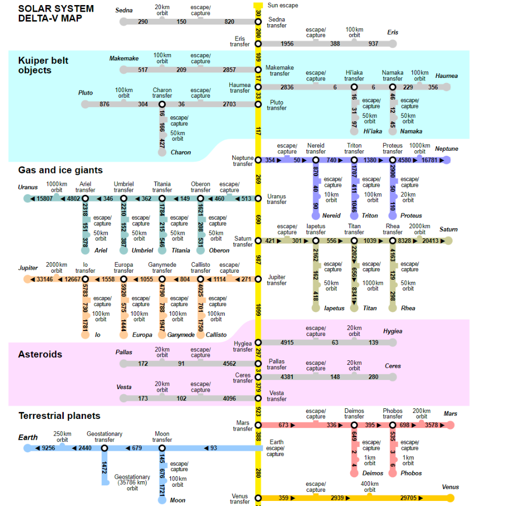
Delta-V Budget
https://en.wikipedia.org/wiki/Delta-v_budget
How small could an orbital rocket be?
https://space.stackexchange.com/questions/18789/how-small-could-an-orbital-rocket-be
Sounding Rockets
https://www.nasa.gov/missions/research/f_sounding.html
Sounding Rockets are used “to Sound” which means to take measurements
usually 30 minute missions, 30-800 miles in altitude for onboard scientific equipment
UN Access to Space for all Initiative
https://www.cubesat.org/news-feed/2021/3/8/un-access-to-space-for-all-initiative
Two basic issues
accelerate the rocket to orbital velocity
Kinetic Energy
lifting the rocket to orbital altitude
Potential Energy
usually at the same time
lbm vs lbf
10pounds mass = 10pounds force on EARTH GRAVITY
10lbm =/= 10lbf in space, on moon, etc.
would scale to ratio of earth gravity
Satellite Weight Classes
https://www.nanosats.eu/cubesat
https://alen.space/basic-guide-nanosatellites/
Satellite Mass Classification
Large Satellite
>1000kg
Medium Satellite
500-1000kg
Small Satellites
Minisatellite
100-500kg
Microsatellite
10-100kg
Nanosatellite
1-10kg
Picosatellite
100g – 1000g
Femtosatellite
10g – 100g
Attosatellite
1g – 10g
Zeptosatellite
0.1g – 1g
<500kg
CubeSat Sizes
CubeSats are nanosatellites defined by CubeSat Design Specification (CSD)
https://www.cubesat.org/
CubeSat Standard
Unit Size 1U
1U CubeSat is 10 cm × 10 cm × 11.35 cm.
2U CubeSat is 10 cm × 10 cm × 22.70 cm.
6U CubeSat is 20 cm × 10 cm × 34.05 cm.
12U CubeSat is 20 cm × 20 cm × 34.05 cm.
Smallest existing CubeSat design is 0.25U and largest is 27U.
Smallest launched CubeSat is 0.25U and largest is 12U as of 2019 January. Very soon 16U from US or 20U from China.
Small Satellite
https://en.wikipedia.org/wiki/Small_satellite
Market
The nanosatellite and microsatellite segments of the satellite launch industry have been growing rapidly in recent years. Development activity in the 1–50 kg (2.2–110.2 lb) range has been significantly exceeding that in the 50–100 kg (110–220 lb) range.[2]
In the 1–50 kg range alone, fewer than 15 satellites were launched annually in 2000 to 2005, 34 in 2006, then fewer than 30 launches annually during 2007 to 2011. This rose to 34 launched in 2012 and 92 launched in 2013.[2]
European analyst Euroconsult projects more than 500 smallsats being launched in 2015–2019 with a market value estimated at US$7.4 billion.[3]
SmallSat Launch Vehicles
Companies offering smallsat launch vehicles include:
Rocket Lab’s Electron (300 kg)[8]
Virgin Orbit’s LauncherOne (500 kg)[9]
Astra’s Rocket 3.3 (100 kg)[10]
Vaya Space’s Dauntless (1000+ kg LEO 600+ kg SSO)[11]
NanoSat Launch Vehicles
NLVs proposed or under development include:
Virgin Orbit LauncherOne upper stage, intended to be air-launched from WhiteKnightTwo similar to how the SpaceShipTwo spaceplane is launched.[34][39]
Ventions’ Nanosat upper stage.[40]
Nammo/Andøya North Star (polar orbit-capable launcher for a 10 kg (22 lb) payload)[41]
As of April 2013, Garvey Spacecraft (now Vector Launch) is evolving their Prospector 18 suborbital launch vehicle technology into an orbital nanosat launch vehicle capable of delivering a 10 kg (22 lb) payload into a 250 km (160 mi) orbit.[21]
Generation Orbit is developing an air-launched rocket to deliver both nanosats and sub-50 kg microsats to low Earth orbit.[34]
Actual NS launches:
NASA launched three satellites on 21 April 2013 based on smart phones. Two phones use the PhoneSat 1.0 specification and the third used a beta version of PhoneSat 2.0[42]
ISRO launched 14 nanosatellites on 22 June 2016, 2 for Indian universities and 12 for the United States under the Flock-2P program. This launch was performed during the PSLV-C34 mission.
ISRO launched 103 nanosatellites on 15 February 2017. This launch was performed during the PSLV-C37 mission.[43]
Resources/References
ASTRONAUTIX
http://astronautix.com/index.html
Space Stack Exchange
https://space.stackexchange.com/
WAC Launch Director Cheat Sheet
https://docs.google.com/document/d/1mU25H3-PgZEyG-IOaMsFwJqUDAx9D0iAWfamnVQWQ1w/edit?authkey=CMivj0I
http://www.washingtonaerospace.org/links.php
Ye Olde Rocket Plans
https://plans.rocketshoppe.com/
https://www.rocketshoppe.com/
RMR – rec.models.rockets
http://ninfinger.org/rockets/rmrfaq.toc.html
https://www.ibiblio.org/pub/archives/rec.models.rockets/
Rocketry Forum
https://www.rocketryforum.com/
Tripoli
https://tripoli.org/
Rocket Reviews
https://www.rocketreviews.com/
USC RPL
http://www.uscrpl.com/
http://www.uscrpl.com/traveler-iv
lots of info/data here
they do experimental rocket designs
List of Missions to the Moon
https://en.wikipedia.org/wiki/List_of_missions_to_the_Moon
https://en.wikipedia.org/wiki/Exploration_of_the_Moon
https://en.wikipedia.org/wiki/Artemis_program
https://en.wikipedia.org/wiki/Timeline_of_Solar_System_exploration
https://en.wikipedia.org/wiki/List_of_artificial_objects_on_the_Moon
https://en.wikipedia.org/wiki/List_of_lunar_probes
https://en.wikipedia.org/wiki/Lunar_resources
List of Inducement Price Contests
Ansari X PRIZE for Suborbital Spaceflight, won in 2004 by Scaled Composites SpaceShipOne
Automotive X PRIZE
Alkali Prize for a process to turn salt into soda ash, won by Nicolas Leblanc posthumously in the early 19th century
Brain Preservation Technology Prize
Brexit Prize[4] – prize for British exit from the European Union
NASA’s Centennial Challenges
The Clay Mathematics Institute Millennium Prize will award to anyone who provides a solution to one of seven important mathematics problems, one was solved in 2003.
Cornell Cup USA, presented by Intel
DARPA Grand Challenge
Egg-Tech Prize by the Foundation for Food and Agriculture Research (FFAR); FFAR and the Open Philanthropy Project are offering $6 million in prizes to improve early detection of a chick’s sex during the egg production process[5]
The Feynman Grand Prize offers $250,000 for a nano-scale robotic arm and computing device that demonstrate the feasibility of a nanotechnology assembler.[6]
Global Security Challenge
Google Lunar X Prize
Intelligent Ground Vehicle Competition
Kremer prize for man-powered aircraft, won in 1977 by the MacCready Gossamer Condor.
L Prize is a US Department of Energy competition to increase efficiency of solid-state lighting.
Longitude prize won in the 18th century by John Harrison
Lunar Lander Challenge
Methuselah Mouse Prize or also known as the “M-Prize”
Montyon Prizes established in 1820, a series of prizes awarded annually by the Académie française
Netflix Prize for predicting user’s rankings of films significantly better than the company’s method, won in 2009.
Orteig Prize for a non-stop flight between New York and Paris, won by Charles Lindbergh in 1927
Peugeot Concours Design
Prize4Life offers between $15,000 and $5 million in prize awards for medical discoveries that remove the largest barriers to finding a cure for ALS (Lou Gehrig’s disease)
Tricorder X Prize
Virgin Earth Challenge
Wolfskehl Prize for proving Fermat’s Last Theorem, won by Andrew Wiles in 1997
ROCKET SCIENCE explained in 15 minutes! And How do satellites work?
https://youtu.be/hZ5mobRcXAU
Old rockets used fins for stability, modern rockets don’t use fins because they contribute extra mass and drag
Modern rockets use TVC – Thrust Vector Control aka “Gimbaled Thrust” by swiveling the output
Liquid rocket engines store propellant in unpressurized tanks, so the tanks are thinner and less massive
Then, to pressurize them before burn, a pump powered by a turbine with own fuel line works on the reactants
Geosynchronous satellites
Sidereal day – matches earth rotation on a fixed reference
since the earth moves around the sun, the sun takes 24 hours to appear in the same spot
but accounting for the drift of the year, the sidereal day is actually 4 minutes shorter
23h 56m 4s
35,786km / 22,236mi
There is only one geosynchronous orbital shell
mass independent
usually centered on equator
launching far from the equator requires orbital correction
geo sats are further away and higher tech
they’re clustered densely over developed regions of the world
the ITU – international telecommunications union – assigns longitudinal satellite slots for geo orbit
https://www.itu.int/en/Pages/default.aspx
LEO low earth orbit satellites are more common, cheaper, lower tech, but require service handoffs constantly as they drift around the earth’s surface
most sats have 2 bidirectional dishes. their main purpose is to receive faint radio signals, amplify, and send elsewhere. the alternative is thousands of link/relay stations
Walrus
Objectives
Finish SOP for Neon Signs, from Consultation through Design and Assembly all the way to Shipping and feedback solicitation
Get 5 orders
Streamline Process
Build an Etsy Shop
Reorganize Lab/Clean out Cubbies
Start Crab Mech
Just start printing things and putting a motor to it
Dive headfirst into the ice cold waters of robotics
Review Chapter 2 at some point before the year ends
Notes
Finished Lab Reorg
There’s probably a file reorg in the works but it can wait another month or two for beginning of next year
May consider a NAS for the future, since Dropbox is $11/mo
Decided to add rocker switch to the parts list for the signs. Included without permanent fix, so client can add or remove at leisure
Need to buy mats still, been holding off.
Print more gridfinity squares
Set up for an 8x print, to run overnight 10h
CLOSE TREESHEETS WHEN SWITCHING COMPUTERS
I had an autosave erase an hour of work…
Ideas
Ionic Thruster???
Check Laptop Claim
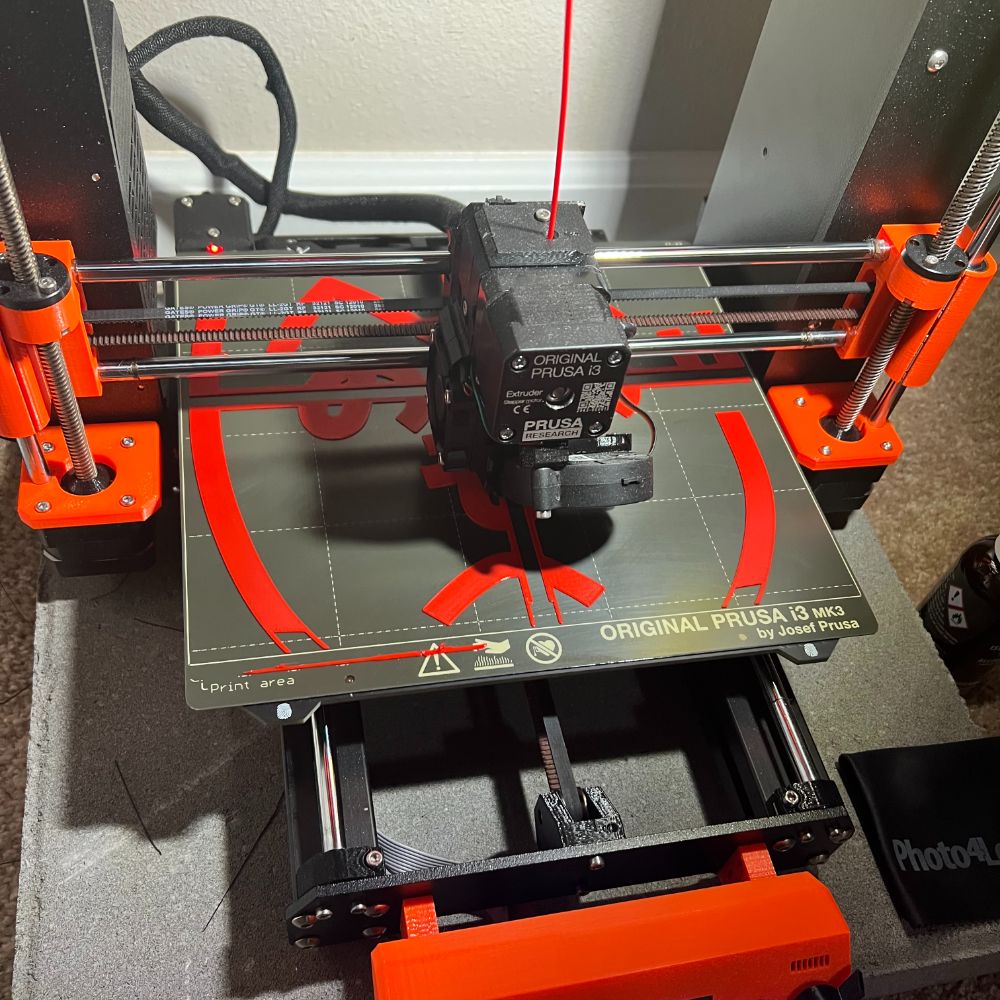
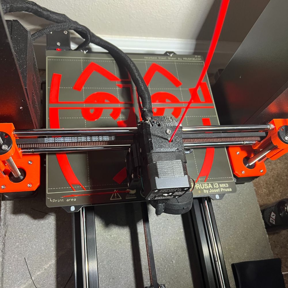
Reference Prusa manual for regular 3D Printer Maintenance
Firmware/Slicer Update
Octoprint
DOES SELF-INTERSECTION NOT COUNT IF YOU PLACE THE PLANE ON PATH IN THE CENTER OF THE PATH? THE TWO 1.0 EXTENSIONS ARE DISTINCT?????
omgggg
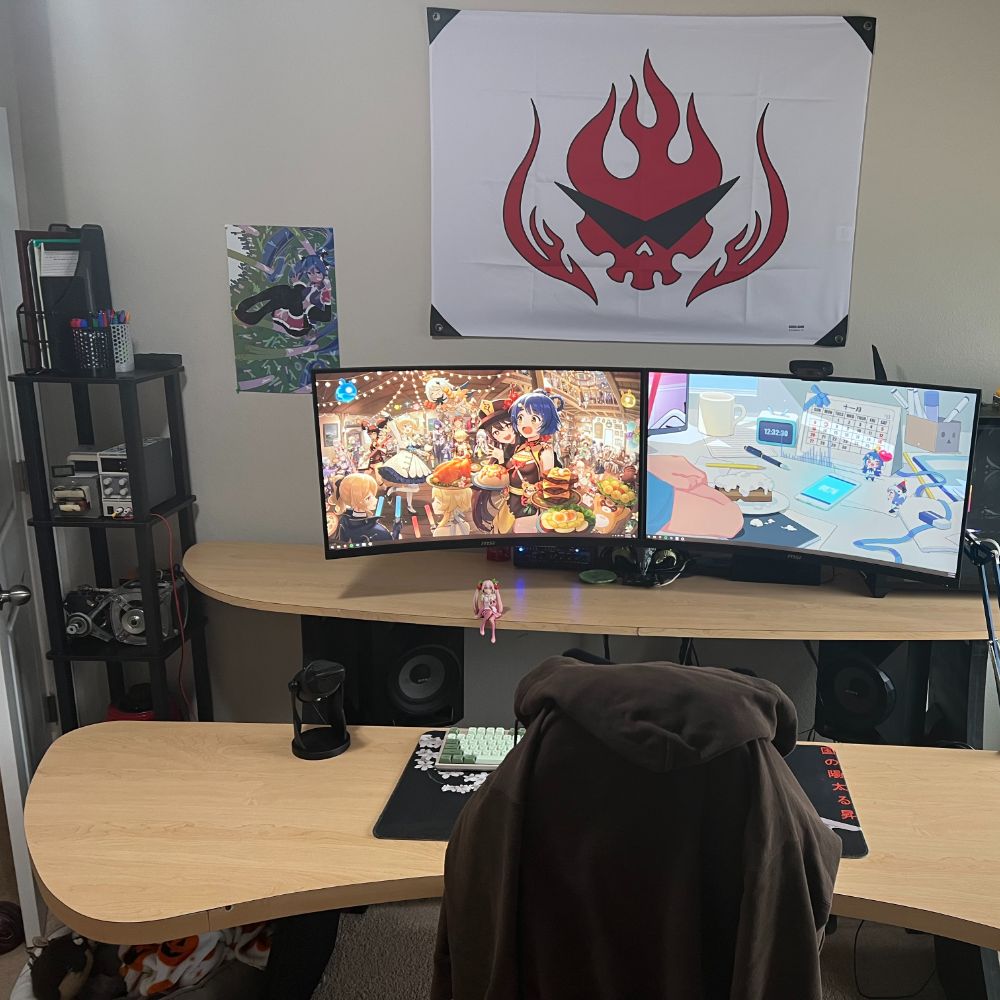
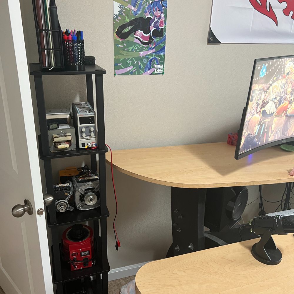
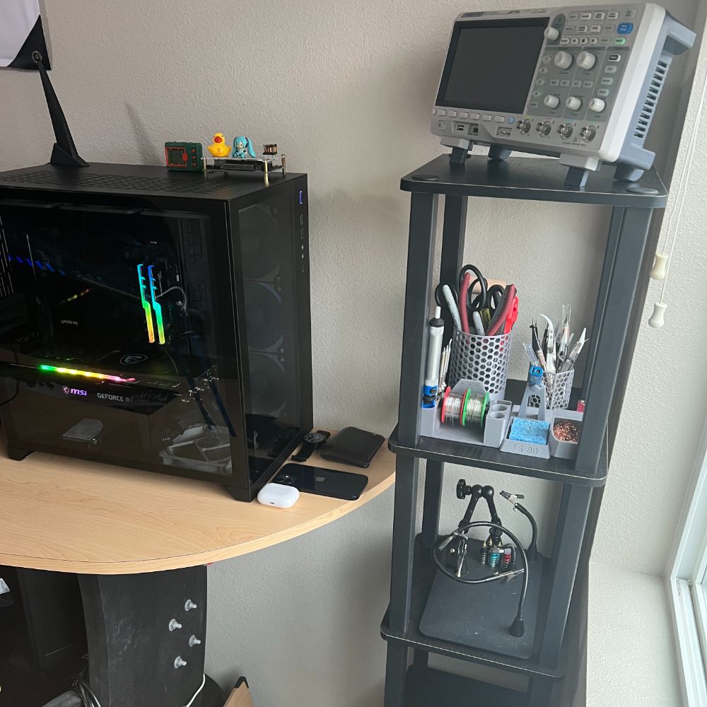
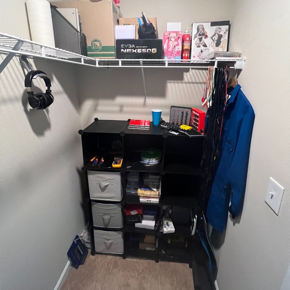
Lab Cleanup
Reorganized everything except small parts boxes
Mainly, unpacked all the cubbies and rearranged everything
Made use of those noctua fan boxes I got from upgrading my PC last month
Moved soldering and tool cups to the right shelf.
The entire upper left wing of the desk is cleared out now. It’s strangely empty
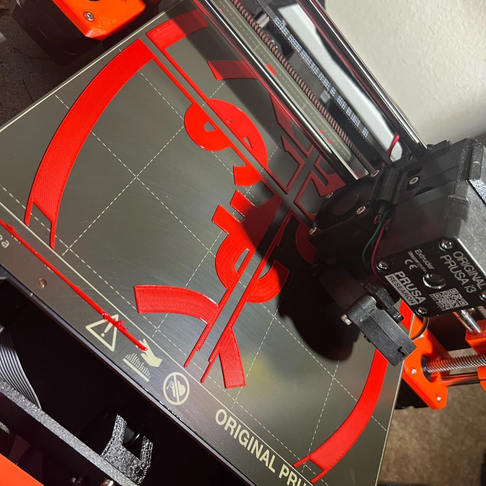
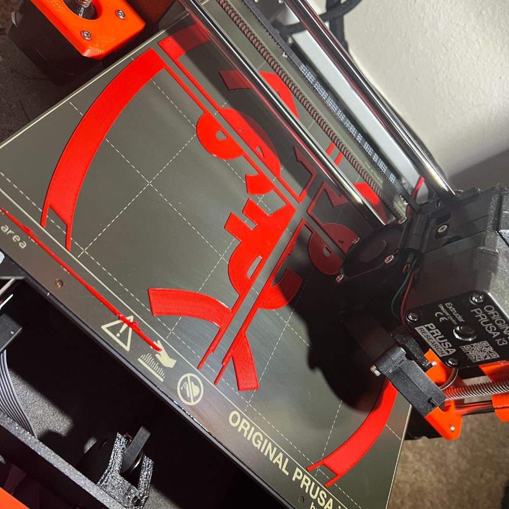
Printer Maintenance, Cleaning, Upgrades, and Repair
Thing is performing worse and it’s driving me crazy
PCA9685
PWM Motor Controller
Missing my blue servos
rip
Pinout
Power
GND
Ground for both power and control
VCC
Logic Power – 3-5V. Match the uC Logic Level.
SDA and SCL pullup point (10kR)
V+
Optional Power Distribution to Servos on Board
6V max
Seems low.
Adafruit says 12VDC is okay, but if you short V+ to VCC it’ll damage the board
Control
SCL
Serial Clock. Has a weak pullup to VCC
Does that mean I have to provide my own external pullup?
SDA
Serial Data
OE
Output enable
Active LOW
When high, all outputs are disabled
Output
16 output ports
3 pins each
V+
Servo Power
GND
PWM
All output ports run at the same PWM frequency
Max Current per pin is 25mA
Logic level for PWM is same as VCC
There is a 220R resistor in series with every PWM pin
Connecting to Arduino
Connection
GND – GND
+5V to VCC
Don’t use Arduino +5V for V+ on the PCA. It’s for logic positive not power positive
2 Pins for SDA/SCL
Arduino Uno SDA/SCL
A4 – SDA
A5 – SCL
Servo Power
Connect an external power source to the PCA to power the servos
It’s recommended to use the terminal block, since it has polarity protection
Apparently, most servos are designed to run at 5-6V.
Some high torque servos will peak at 1A each. It seems the board can’t handle this
Each pin is rated at 25mA, so I’m guessing larger power applications will have power and ground for the motor wired in separately, and only the PWM signal pin
Thru-Hole Capacitor Slot
The PCA comes with a slot for an electrolytic capacitor that can be soldered in
It’s purpose is to buffer the power supply during peak motor current draw
Recommends n * 100uF where n is servo count
The boards I purchased come with a 1000uF already
Board chaining
The boards can be chained. All you really need is a 6 pin ribbon cable
In order to use chained boards, they need unique addresses
There are six pairs of separated solder pads at the top of the board. Soldering these together changes the address of the board
The default address is 0x40
soldering the right most pad together (LSB) changes the address to 0x41
when chaining boards, the software requires a distinct object to be declared for each address.
Software
Adafruit has the library for this
Adafruit_PWMServo
Example sketch “servo” works as is with my motor
Motor
I’m using a MG995 Servo Motor
Some specs on it:
https://components101.com/motors/mg995-servo-motor
Metal geared servo for more life
Stable and shock proof double ball bearing design
High speed rotation for quick response
Fast control response
Constant torque throughout the servo travel range
Excellent holding power
Weight: 55 g
Dimension: 40.7×19.7×42.9mm
Operating voltage range: 4.8 V to 7.2 V
Stall torque: 9.4kg/cm (4.8v); 11kg/cm (6v)
Operating speed: 0.2 s/60º (4.8 V), 0.16 s/60º (6 V)
Rotational degree: 180º
Dead band width: 5 μs
Operating temperature range: 0ºC to +55ºC
Current draw at idle: 10mA
No load operating current draw: 170mA
Current at maximum load: 1200mA
Notes
In the circuit if microcontroller and servo has different power sources then the microcontroller ground needed to be connected to servo ground.
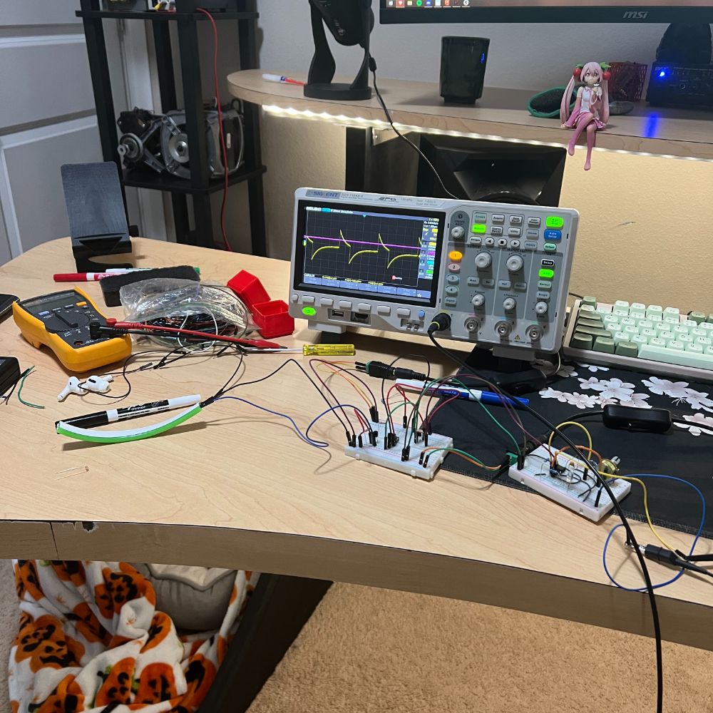
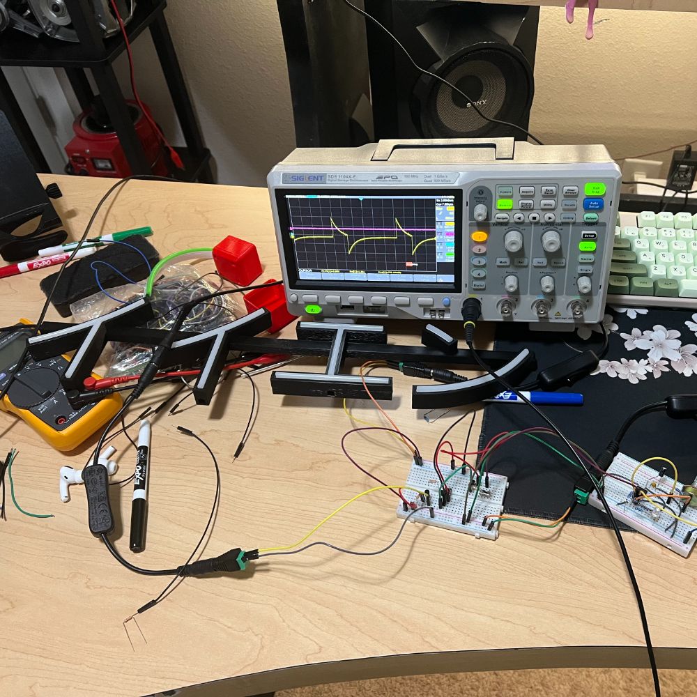
Frequency of PWM:
MG995 takes in PWM signal of frequency 50Hz and any higher and lower frequency PWM will lead to error. As shown in figure the every single cycle of PWM needs to be 20ms width for 50Hz frequency.
Duty cycle of PWM:
The duty cycle of PWM (or ratio of ON time to total cycle time) determines the position of servo axis. If we provide a PWM signal of 0.5ms ON time over 20mS complete cycle, the servo axis will move to 0º.
1000ms in 1S. 50Hz means period of 20ms
0.5ms ON over 20ms total = 1/40th duty cycle = 2.5%
0.5ms/20ms = 2.5%ON => 0 deg
1.5ms/20ms = 7.5%ON => 90 deg
2.5ms/20ms = 12.5%ON => 180 deg
Calibrating Servos
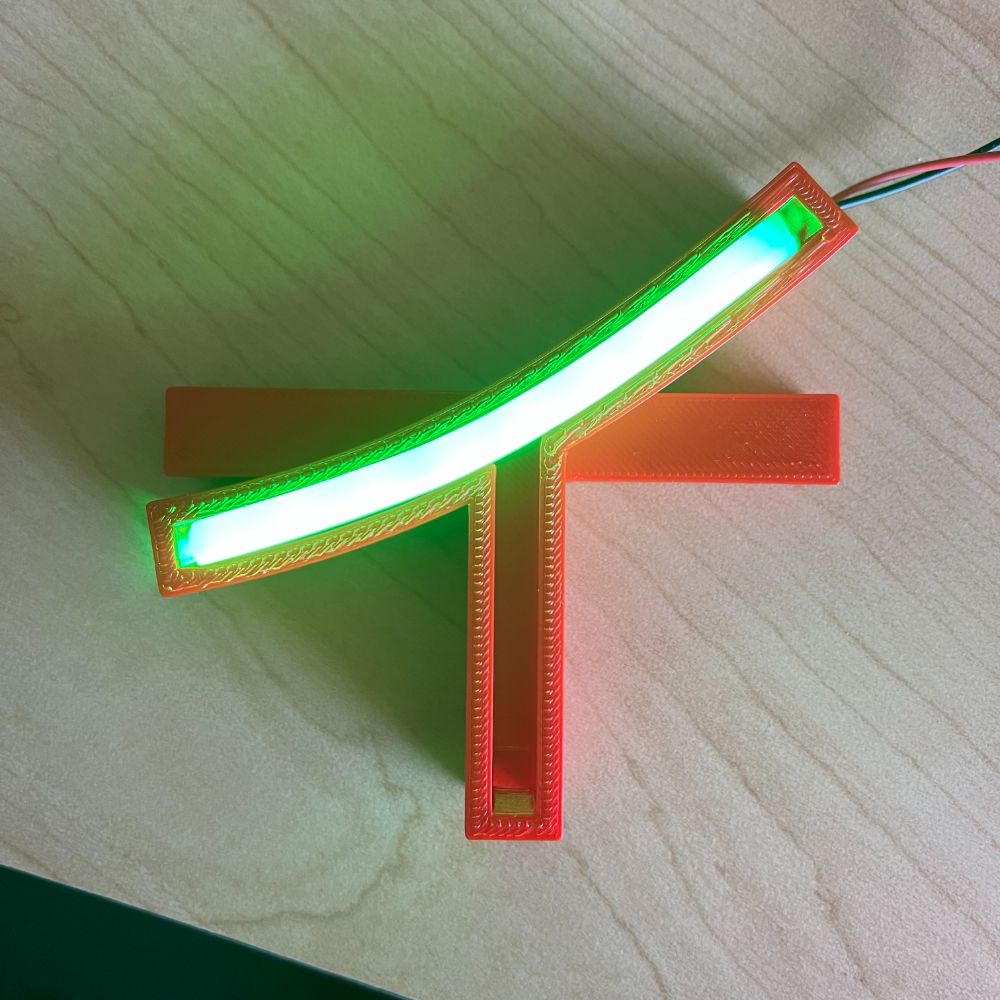
NFS – Neon Flex Signs
SOP
Getting Orders
Soliciting Friends
Requesting a Design
Requesting a Size Profile
Consult Angel’s Costing Workbook
Offering a Quote
Agreeing on a Quote
Offer a Timeframe
Order Placed
Design Received
Size Picked
Colors Picked
Quote Approved
Money Received
Completing Orders
Documentation
Document Order
PRE:
Order Number
Order Date
Money Received
Priority
Estimated Cost
Color/Color
# of Segments
POST:
Time taken to fulfill order
Labor taken to fulfill order
Design
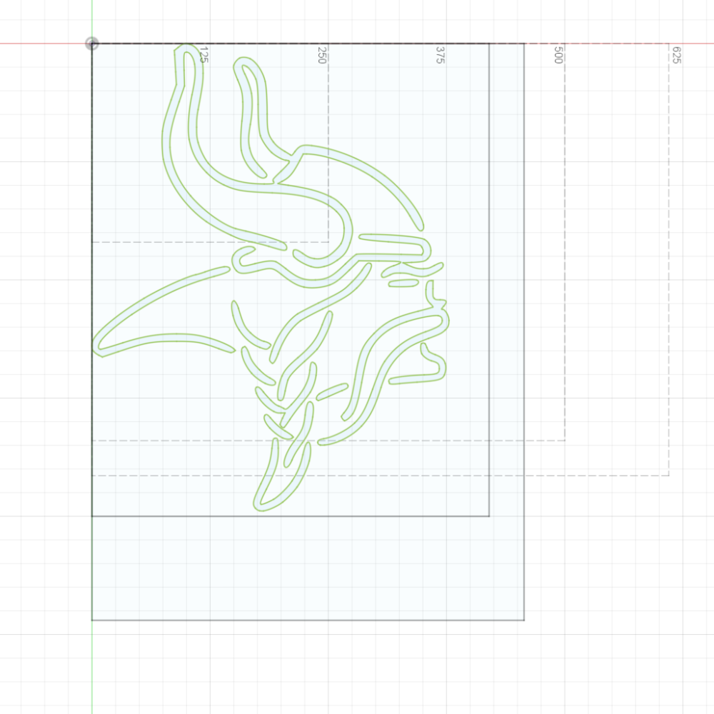
Step 0 – Getting Started
Create new F360 Project with Order Number
Lay out references
Shipping Box Size
3D Printer Bed Size
SVG
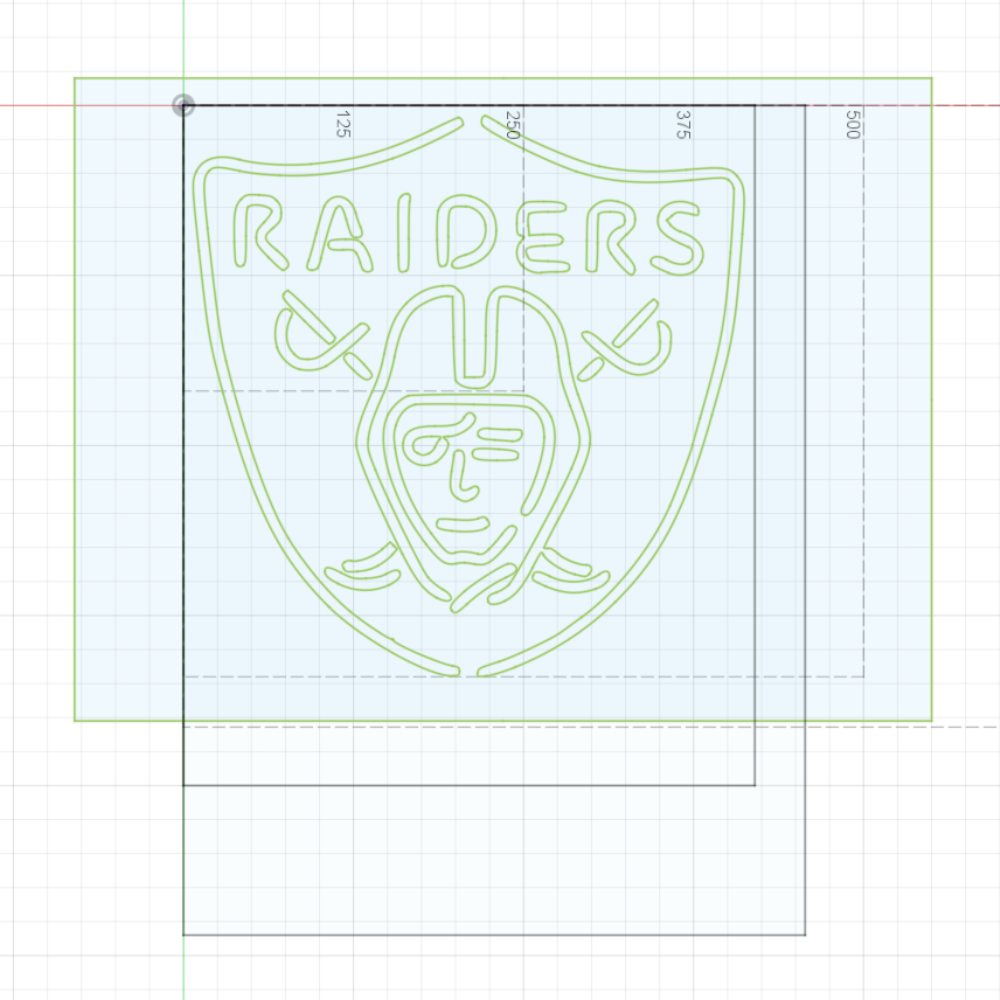
Sizing
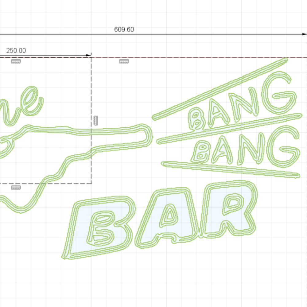
Adjust the SVG of the image to match client spec
Document the Image Scale of the SVG
Document the Total Profile of the SVG
Leave margin to the shipping box for bubblewrap
Zoning
Create several 3D Print Bed Rectangles (250x210mm)
Lay out the different zones the print will be carved in to
Estimate what the zones will be, how many there will be overall, and which will be male/female
Once decided, create a master ZONING sketch that captures this info
Rails
Decide on the minimum number of Rails necessary to structurally and electrically link all distinct pieces in the design before proceeding
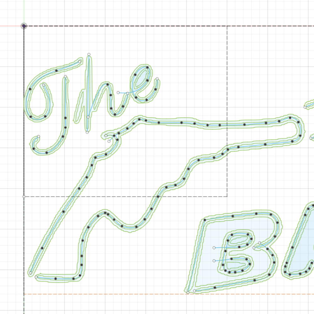
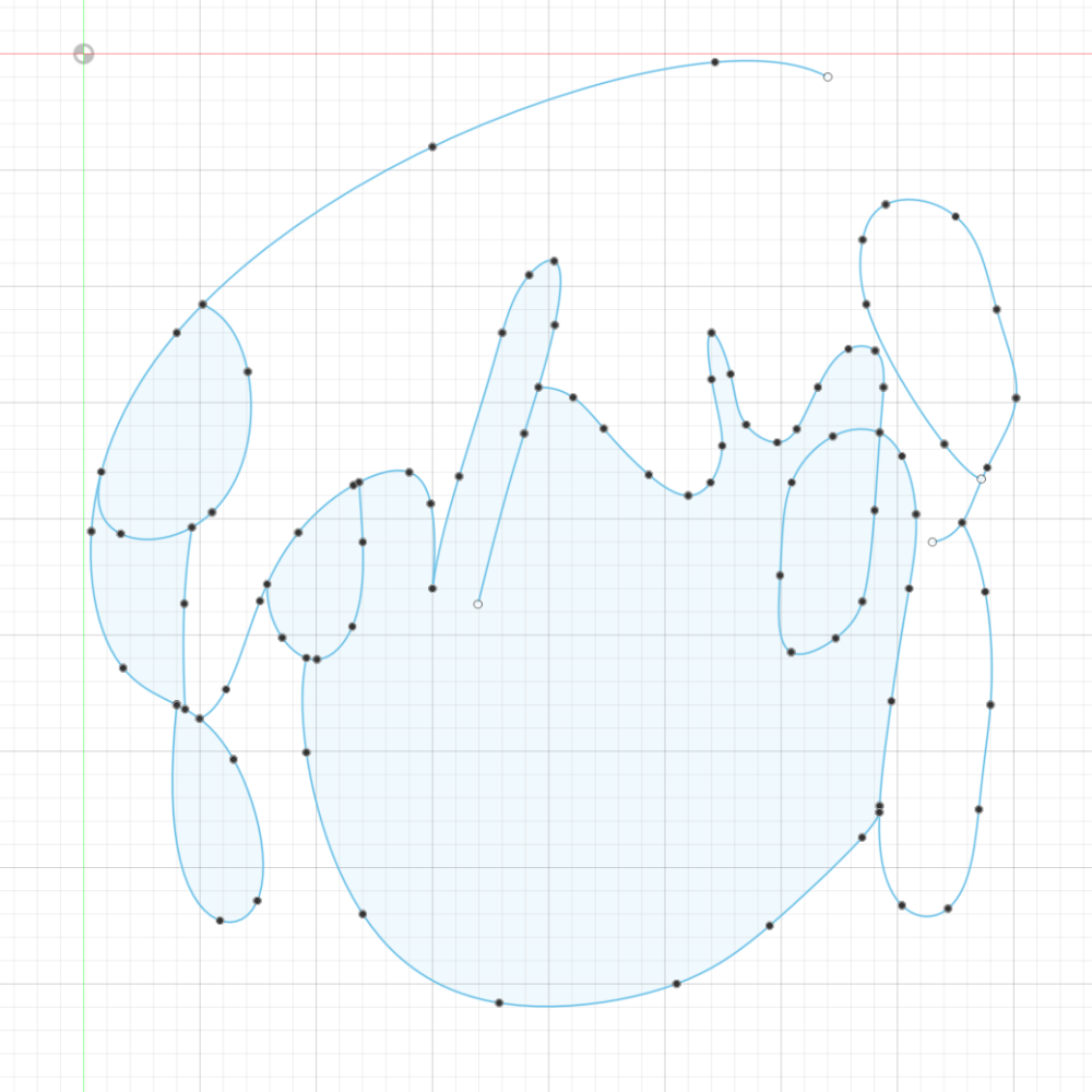
Step 1 – Setting up PATH
Create a new sketch for PATH
Use splines and lines to trace out the light path
In areas where the curve will intersect, fold back on itself, or turn abruptly
Run two distinct line segments through eachother with significant extra length
These will be extruded separately, joined to the same body, and cut out later
Adjust lines and splines of PATH until satisfied
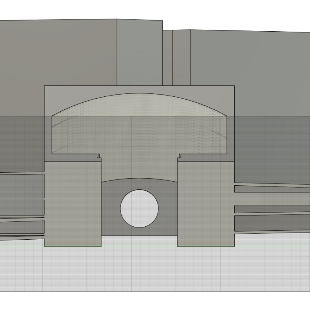
Step 2 – Profiling
Construct a Plane along Path on one of the path segments
Build the standard profile for the Channel/Tunnel structure
Copy it
Repeat with new path-planes for each unique path segment
* when pasting, the profile may appear upside down. use the movement box to set the pivot to the hinge point and rotate it 180 so it looks right
* when building/pasting the profile, make sure the origin point of the constructed plane intersecting the path segment is selected. Everything will be wrong if this is not the anchor point for the profile
Once every profile has been laid out, rename them all to ProfileN for clarity
One by one, select each profile, and its respective path, and run a Sweep on it.
The first instance will call for new body. Each subsequent instance should join into the original body, if possible.
* be sure to select both the channel and tunnel zones of the profile at this point. The lower-level tunnel will be cut out later after Carving
Once finished, all profiles and all path segments will be 3D sweeped. The hard intersections will have extra length that need to be carved out manually.
Before proceeding, adjust any lines or splines from the PATH to make sure the channel determined by it looks appropriate. This is difficult to change later.
Step 3 – Carving
Hard Intersections are points where two distinct lines/splines cross eachother
Create a sketch referenced to the top surface of the channel walls
Create zones, internal and external
Internal – rectangular zone around the blockage walls
External – zone around all the extra stuff after the intersection that needs to get deleted
Reverse extrude internal walls 10mm to flush with the floor of the channel
Reverse extrude external zones 20 or 30 mm to completely erase everything beyond the corner/intersection point
Change perspective slightly to see if there are any thin slivers of material still existing.
If so, reverse extrude them -0.1mm usually gets rid of them.
* It is important to make sure that all of these are caught and cleaned up. Otherwise, there will be additional bodies in the object further down that are very hard to identify.
Repeat for all hard intersections until the entire Swept PATH looks appropriate
Step 4 – Railing
Now that the design has been Pathed, Swept, Profiled, and Carved, it’s time to add the support rail
Create a RAIL sketch similar to the PATH one
Create perpendicular rails using straight lines that use the minimum number of segments to physically and electrically link all of the distinct sections of the design
Once the RAIL sketch is complete, create a path plane and draw up the Rail Profile
If there are multiple Rail lines, repeat as necessary
Sweep out the Profile along the Rail Path and be sure to include the tunnel as solid for now
This process should join every last part of the design into a single body
Step 5 – Tunneling
Now that the design has been Pathed, Swept, Profiled, Carved, and Railed, it’s time to tunnel through everything
RAIL first. PATH second.
* Selectively toggle visibility of solid bodies in order to properly select the profile zones and paths for this part
Select the RAIL’s tunnel profile zone and the path, and run a CUT SWEEP through it
Once all the rail’s runnels are cut out, do the PATHs
Go through each PATH’s profile and sweep path, and run a CUT on the tunnel zone. This should pass clean through any rails.
Once complete, check the underside. The Rail’s main channel should have cuts for each distinct segment’s tunnels to flow into it.
Not catching a blocked wall here will create issues down the line during printing and assembly. Double check this part.
Step 6 – Walling
Create a sketch referenced to the floor of the Channel, from the top
Create walls of equal thickness at the terminal point of each segment until the entire thing is contained.
Do this by drawing rectangles at each end of each segment and then extruding upwards 10mm
Step 7 – Porting
Now, go to the endpoint of each strip, where it meets the wall, and create a full size hole in the floor of the channel, 5mm along from the wall.
Do this on both endpoints for every segment, for flexibility in wiring in the future
This allows the wire to drop down to the tunnel layer, and this hides the wires overall.
Step 8 – Sectioning
Now that the Design has been completed, the next major step is to carve it out into interlocking pieces that can fit within the print bed
First, Copy the Object and Paste it into a new Component.
Then, Copy in the ZONING Sketch into that new component as well.
Then, Copy in the PATH Sketch as well
Rename the Component and Rename the Object itself to be ###-BASE
Create Duplicate Components for each distinct SECTION as determined in Step 0
Rename each Component and Body to ###-SEC-N
Now, Activate the first Section’s Component,
Toggle visibility OFF for everything else not related to this Component
Select Every Zone except for the Zone for this Section
and extrude to cut away and delete everything but the portion of the design within this zone
Next, create the male and female adapters
Create a new sketch referenced to the floor of the channel
Enable visibility of the PATH sketch, and use it to line up a 10mm straight line to a point along the path, anchored at the center of the edge of the floor of the channel
Create an identical path, or reference the original path
Reference the cross section of the channel, create a new sketch, and draw out the adapter profile
Select the adapter profile, and the PATH, and then Sweep along the path to extrude out a curved profile that confirms to the path.
Then, adjust the length of the sweep’s travel by hand until it conforms with the 10mm line created earlier
Go a little short for males, and go a little long for females, that way the male never exceeds the size of its slot and pushes out
Double check that the section doesn’t exceed 250x210mm the print bed size
Repeat for every section of the print
Once all sections are complete, double and triple check that all the pieces will fit into eachother by toggling visibility for everything and ensuring every male is matched to a female of slightly larger size, and that everything will fit onto the print bed individually
Step 9 – Export
Select each object, and one by one, export for 3D Printing
Save in the NFS-STL Folder under a subfolder for the project #
Open each print in the Slicer and be sure to select the settings profile that excludes the outer rim/brim from the print to maximize available print area
Double check the print looks correct in the slicer, which has an easier to use camera
Verify all the tunnels are continuous, nothing got skipped, etc.
Export G-Code files into a G-Code folder under a subfolder for the project #
Printing
Print them one by one, make sure they look good
IPA on the bed before the print, check first few layers,
Let cool all the way before retrieval, to prevent warping
Testing
Make sure all the pieces fit together as intended. Make sure the structure is stable
Cutting
Cut the Neon Flex to length for each section
Do this by lining up the free edge to one wall of the segment, and lining up an exacto with the opposite wall face up and scoring the underside of the flex line
From there, cut it off at that point with the flush cutters, and examine
If solder pad placement at that exact length is bad, it’s possible to cut the free end beforehand to “slide” around on the PCB pattern.
You can cut about 20% to either side of the black cut line for more or less solder pad room
Make sure each segment is cut to as close to full size as possible, the fit should be quite snug.
Make sure each segment has sufficient solder pad to work with, and orient the strip so that wiring will be easier
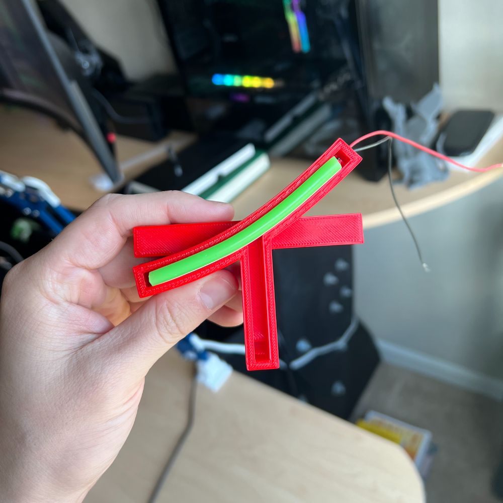
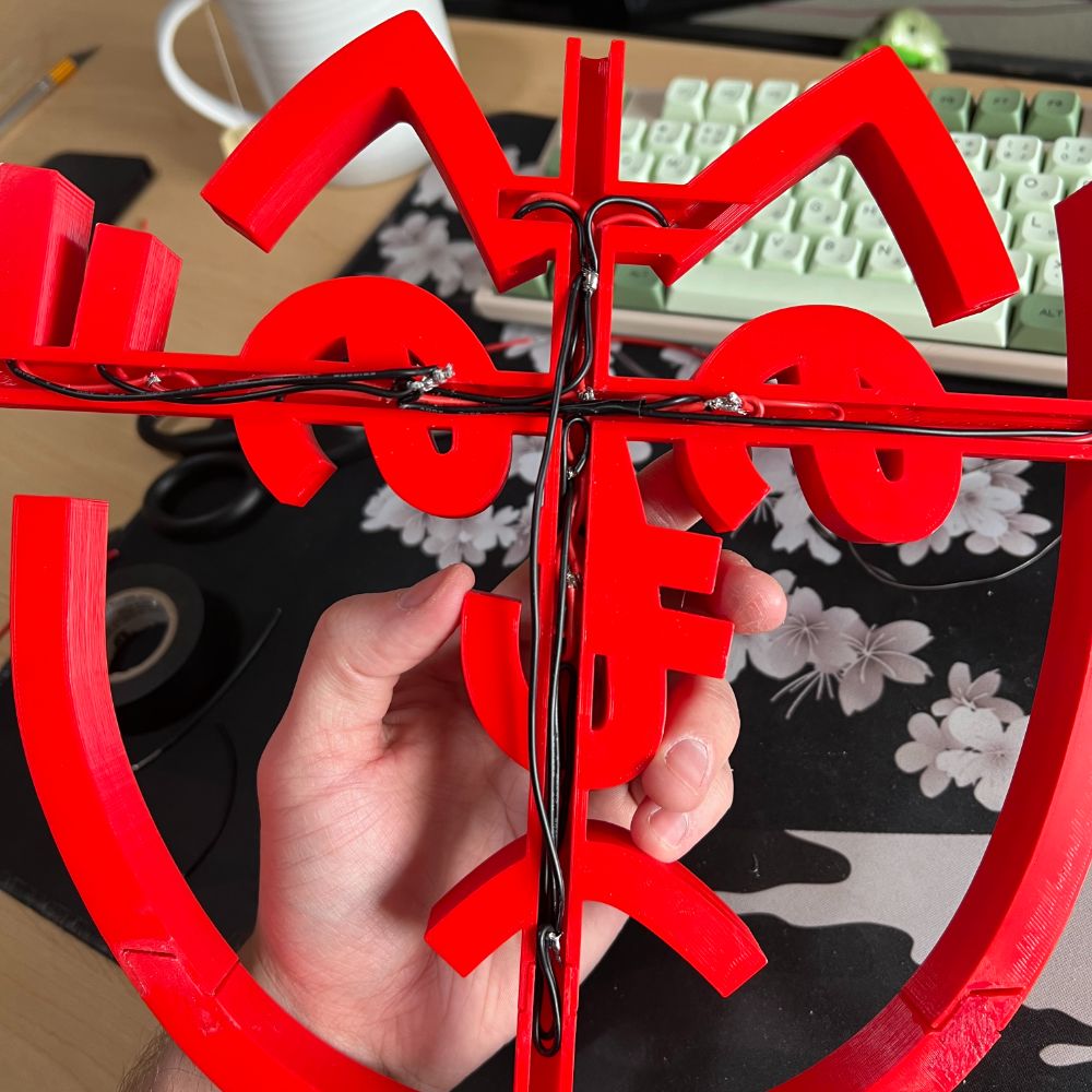
Wiring
Get 2 colors of 22AWG stranded wire
Cut to length notably longer than the length from solder pad, down through tunnel, to rail
This leave wiggle room once it meets the rail
Strip both ends of both wires. Twist if necessary
Tin, and then cut to a short nub
Add solder to the solder pads of the LED strip
Bring the tinned nub and the pad together, heat and join
Make the connection as flush as possible
Always double check the wire colors. Black on square side (bottom) red on round side (top) +12V/GND
Once connection is set, fold wires down flush/perpendicular harshly and route through port into tunnel
Use tweezers to guide wires through to the main rail
Once wires are through, check functionality with alligator clips
Repeat for every LED Segment until the entire thing is wired up
Bussing
Because every wire for every segment is significantly longer than necessary, they can be trimmed to a uniform post-route length, stripped, and then joined onto a single wire.
This requires them to be long enough, otherwise the whole thing gets messy fast.
Use distinct sections of 22AWG wire/solid or stranded to connect positive and ground lines to eachother
This is tedious and pretty slow
Once Everything is connected, test with alligator clips and ensure everything lights up at once
Be wary at this point, as some lights may burn out at the edges due to bad connections, torn solder pads, or tinned nubs being too long and contacting other components
Once everything is working and the wires are sure to not contact eachother
Cut a stirp of the sheathed 2-conductor black wire, strip and trim the inner wires to match the bus nodess and then have it run off the side.
It should be another meter or so long after leaving the print
From there, slide on the wire panel covers, get the whole thing cleaned up, mount and test again
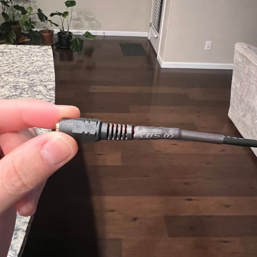
Finally, strip the other end of the meter long main cord, solder to the female barrel jack adapter, and heat shrink the connection to make it smooth and connected
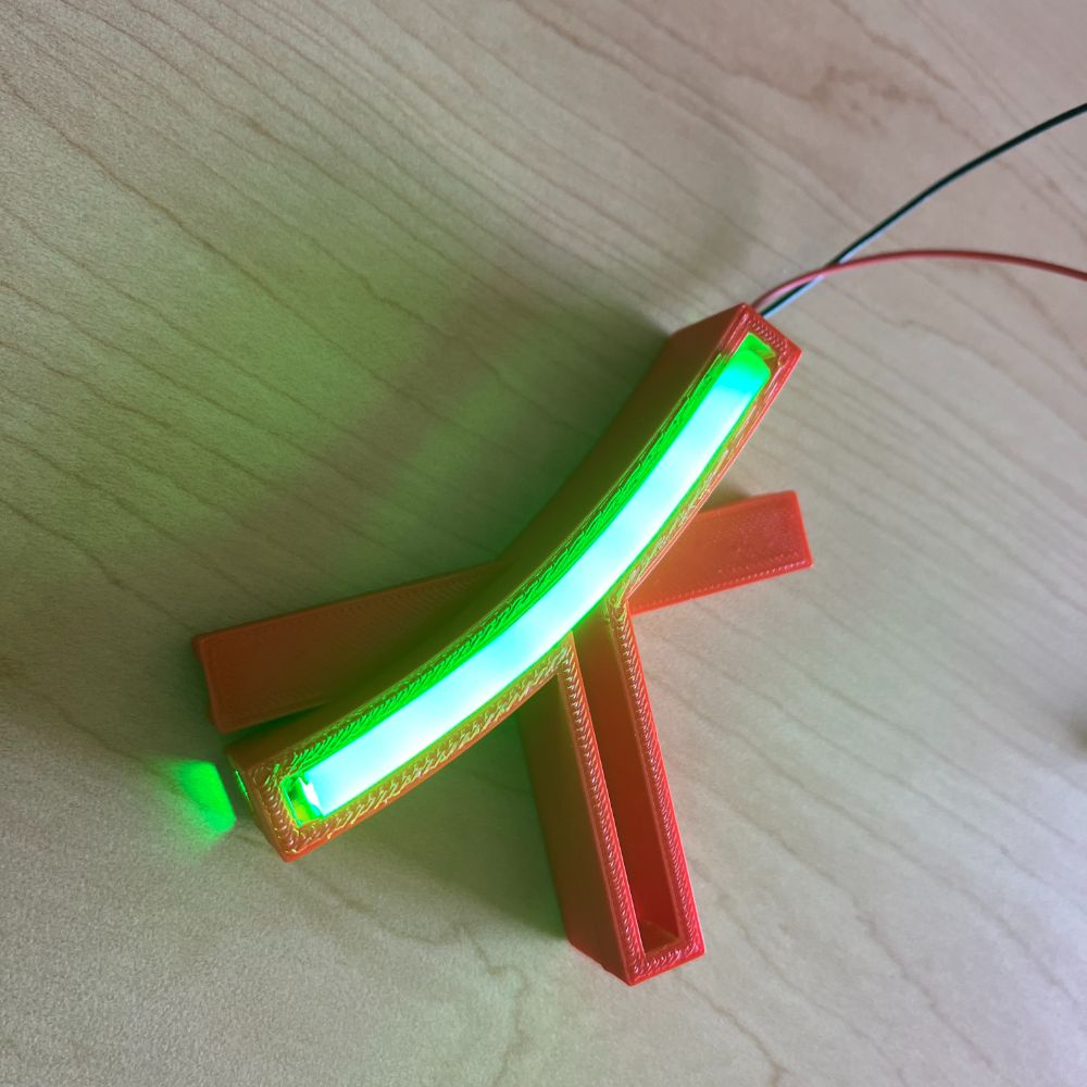
Testing
Leave on for several hours, check heat, wiggle it around, bang it a bit, make sure it’s at least moderately durable
Shipping
Line the inside of the box with bubblewrap
Wrap the product in bubblewrap 1-3 times as necessary
Add 12V adapter and inline Barrel Jack Switch
Add Thank you Note
Seal up and prep for shipping
Use Pirate Ship to print shipping label
Send out
Notes
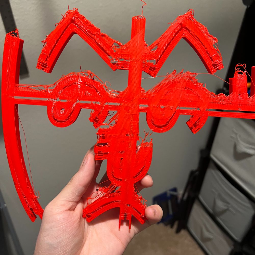
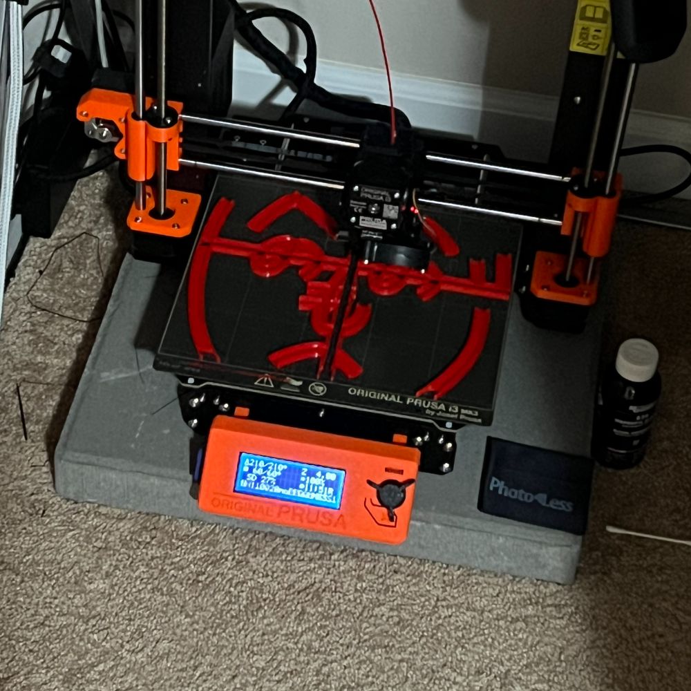
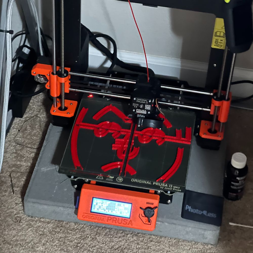
Was printing Heno and I kept getting an error where after about two hours it just shifts the whole thing a cm and makes a mess.
https://www.reddit.com/r/prusa3d/comments/sp1rqp/open_edges_alert_in_prusaslicer_how_to_fix_if/
says here i can just right click the error talking about open edges and it’ll fix the STL
SO I simplified the STL at very high resolution in Prusa slicer, and then right clicked the 3 remaining open edges warning and it says no errors detected.
the glitch happens about 2.5 hours in, so we’ll see if it happens again
RULE OF THUMB 0.6A/m
12V 2A more accessible than
Small Curve Modeling
For a small uppercase B, it’s difficult to model
First, it’s based on a sweep:profile+path+guide rail system instead of just the profile and path
Second, this systems only fixes the high curvature crashes, it still can’t intersect with itself during the sweep
Third, when the guide rail is active, you can no longer sweep in both directions at once, if the plane is placed in the middle of a path.
This means that the guide rail sweep needs to be done two times, with two constructed plane on paths, such that they cross eachother in the narrow gap between them, so the bodies can be joined properly
the guide rail doesn’t need to be very precise, but the path ought to be
the profile swept along should also be anchored to the path on its corner to maximize curve capacity
as long as the profile intersects both the guide rail and the profile at the start point, the sweep should work fine. They don’t need to be anchored on the plane of the profile, just passing through